
Recent updates:
2024-06-03 08:00 (UTC) New topic: Scripts (Upcoming feature).
2024-04-19 07:50 (UTC) Reading the Modbus data type Coil with the option Read full bytes does not work correct in the test run mode.
2024-02-20 11:35 (UTC) New topic: Text color
2024-02-16 05:25 (UTC) The As text format is not working correctly for DW variables in the Test run mode.
2024-02-06 13:55 (UTC) New topic: Connection types
2024-01-13 06:50 (UTC) New topic: Number formatting
2023-12-01 05:35 (UTC) New topic: Protect panel (page)
2023-11-05 11:30 (UTC) New topic about Device settings in HMI Droid Studio
2023-07-28 03:25 (UTC) New topic about Modbus addresses
2023-04-17 01:40 (UTC) Reading from the Siemens S7 data blocks above byte address 4095 can show incorrect values.
2023-03-09 19:30 (UTC) Customized scaling of analog inputs in a Siemens LOGO!
2023-02-27 03:00 (UTC) Very fast swiping when using a button with a password for navigation can make Odrid HMI crash.
Contents
HMI Droid (Odrid HMI) - The app
- Channels
- Launch screen
- Title row
- Menu
- About
- Workspace
- Configure HMI Droid
- Panel information
- Communication diagnostics
- Import file
- Delete
- Create and edit panels (pages)
- Transfer files to an Android device
- Transfer files to an iOS device
- Polling optimizer
- Communication parameters
- Windows version (Alpha)
- Odrid HMI for macOS
- Windows Subsystem for Android (WSA)
HMI Droid Studio - The development tool
- Download HMI Droid Studio
- Using the HMI Droid Studio
- File versions
- Naming panels (pages)
- Background
- Panel properties
- Grid
- Objects
- Font
- Character set
- Text color
- Text background
- LED type
- Position
- PHYS (Scaling)
- Scripts (Upcoming feature)
- Address format
- Communication parameters
- Device settings
- Connection types
- Communication protocols
- Protocols and connections
- Variable areas
- Modbus addresses
- Modbus data types
- Modbus word order
- Control word with life bit
- System registers
- System flags
- Test run panel (page)
- Protect panel (page)
Appendices
- Addressing variables in xLogics PLC's
- Addressing variables in Koyo Click PLC's
- Addressing variables in Schneider Electric Modicon M221 PLC's
- Eaton easyE4 programmable relays
- Siemens S7 PLC's
- Siemens LOGO!
- Siemens 1200/1500
- Customized scaling of analog inputs in a Siemens LOGO!
- Checklist for troubleshooting communication issues
- Port server setup example
- Known issues
Channels
Channels are used to connect different objects in the same panel (page) to multiple PLCs (or other devices) concurrently.In HMI Droid Studio 6.7.8.3078 and later, the communication parameters can be defined for up to eight (8) different channels.
Most Objects have a new Channel property in the range [0,7] to connect the Object to a certain Channel.
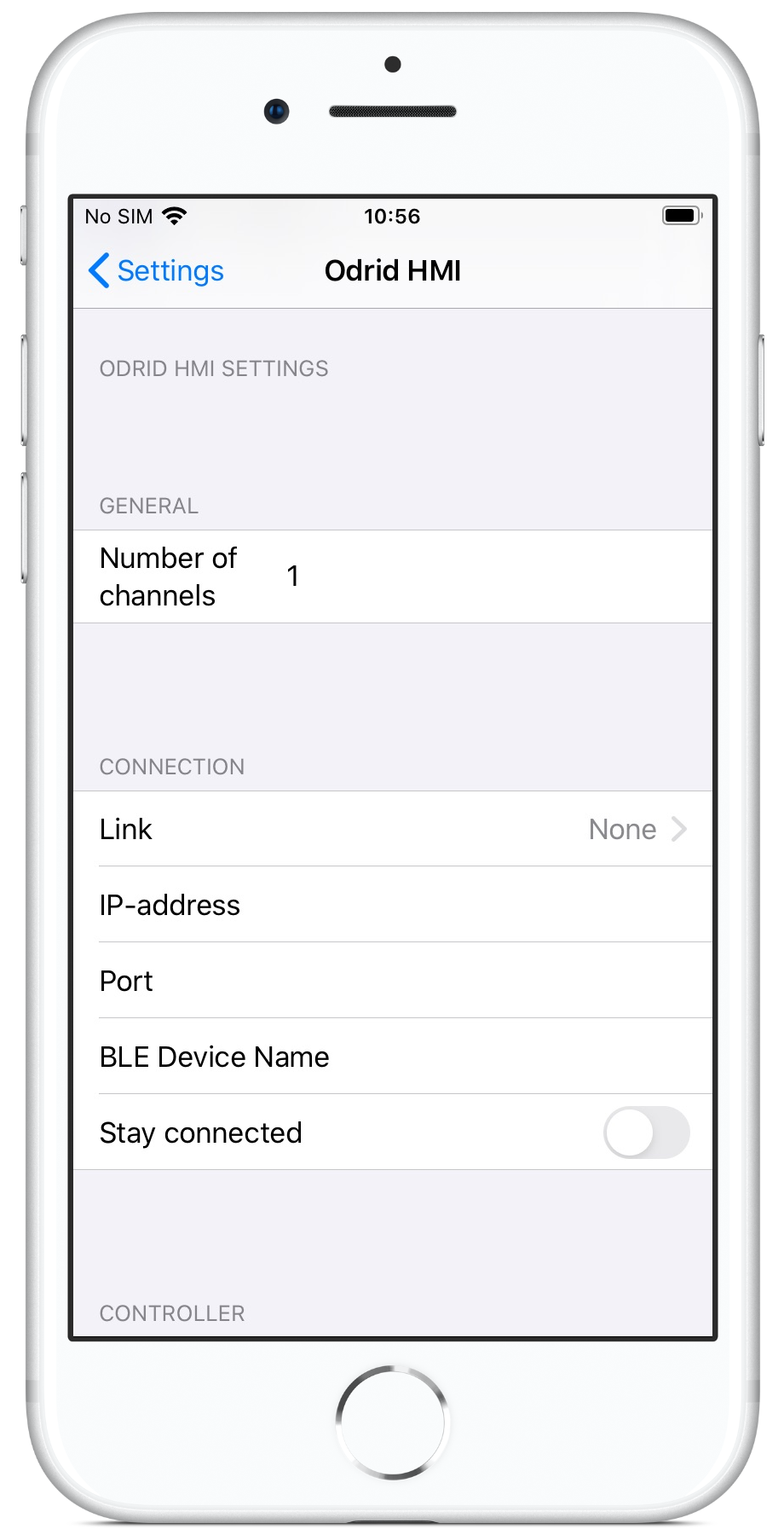
To use multiple Channels, the (new) setting for Number of channels in the app must be increased. The defult value is 1.
After increasing the setting for Number of channels, the app needs to be fully closed and started again for the change to take effect.
Note: When using multiple channels, at least some of the communication parameters must be entered in HMI Droid Studio. Any values entered in the settings in the app will be used as default values for all channels.
 |
 |
Launch screen
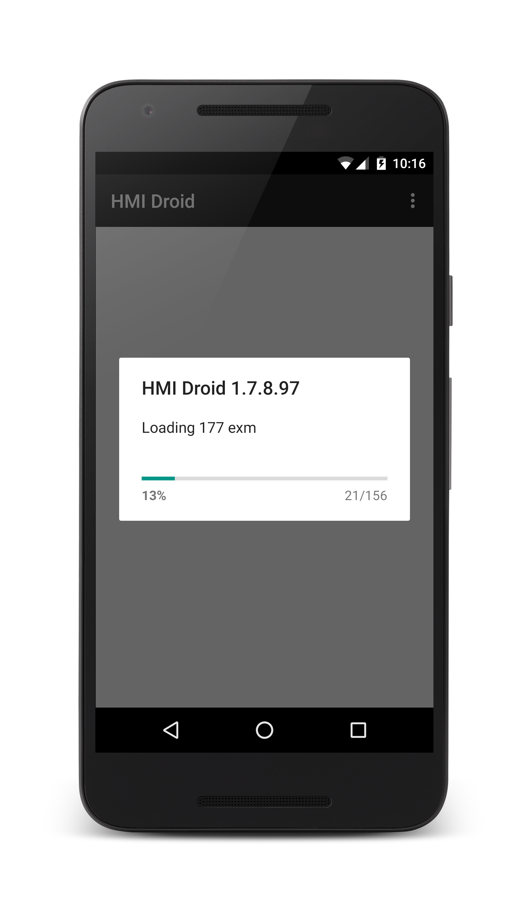
The Android version of the app displays a progress indicator while loading the panels (pages).
|
|
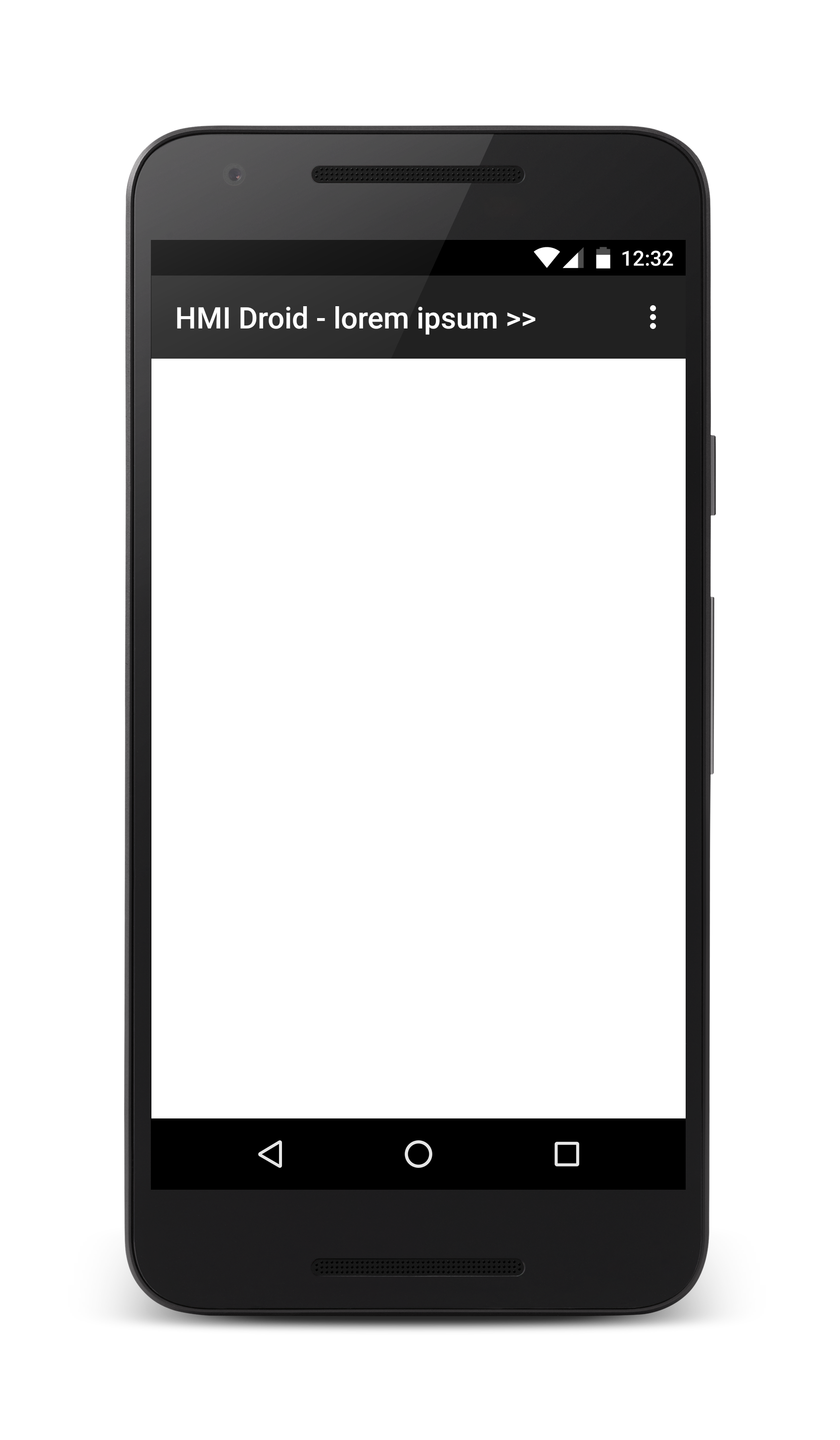
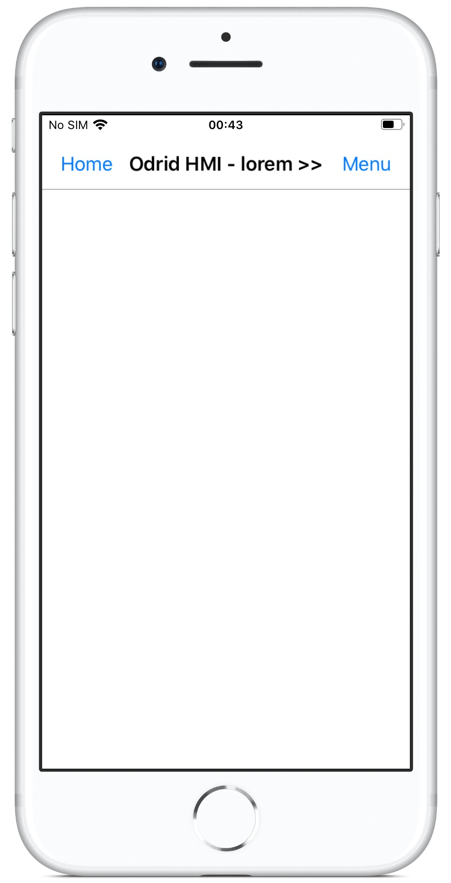
Title row
The Title Row displays the name of the current panel (page). If there are panels (pages) to the right of the current panel (page), a>>symbol is displayed after the name.
In the iOS-version of the app, there are two buttons in the Title Row (or Navigation Bar). Pressing the left button will navigate to the start panel (page). This button is hidden or disabled when the start panel (page) is active. The right button will open the menu.
On iPhones, the space for displaying the app title and the name for the panel (page) is smaller than on most Android devices and long names might be truncated.
|
|
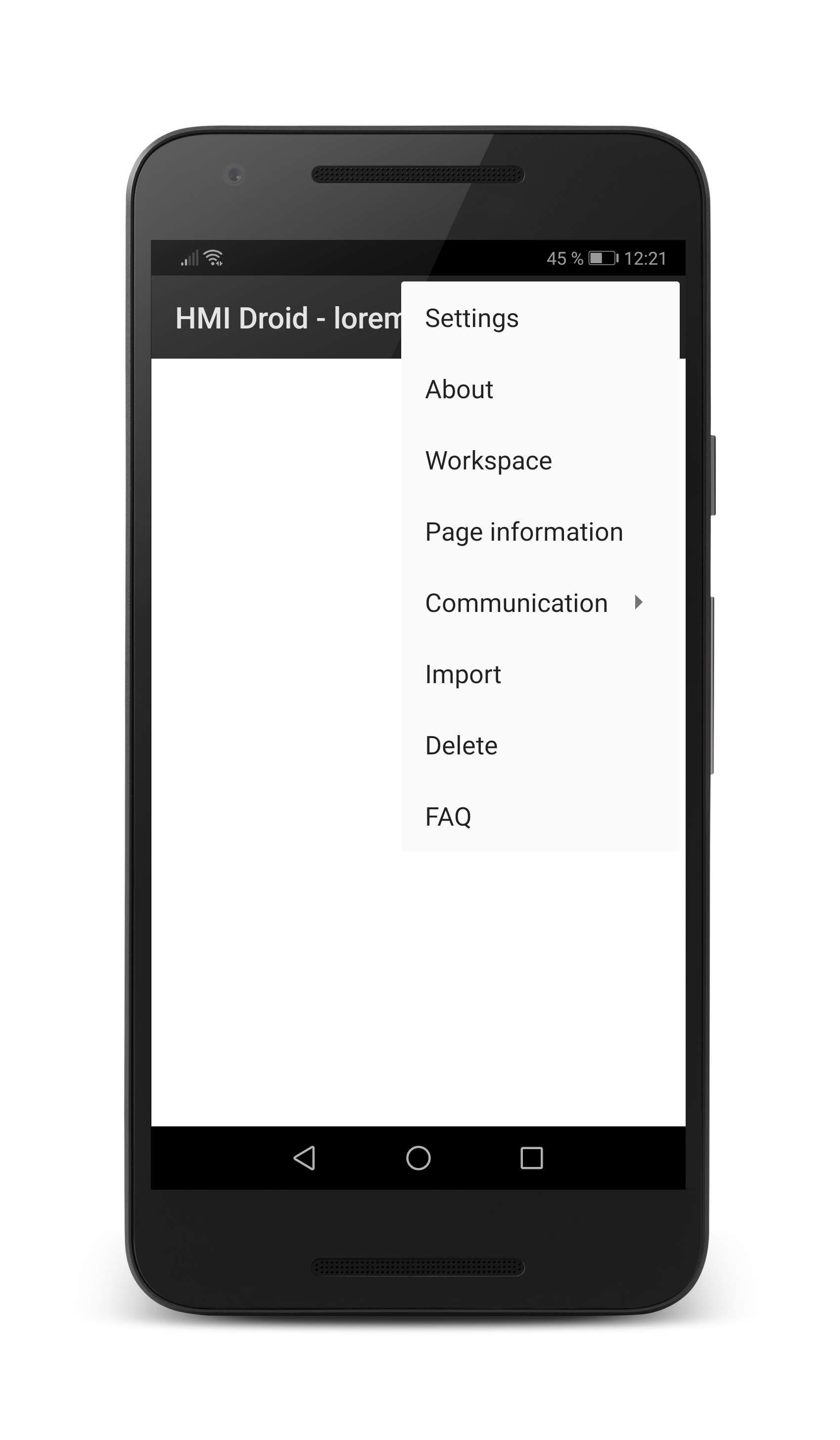
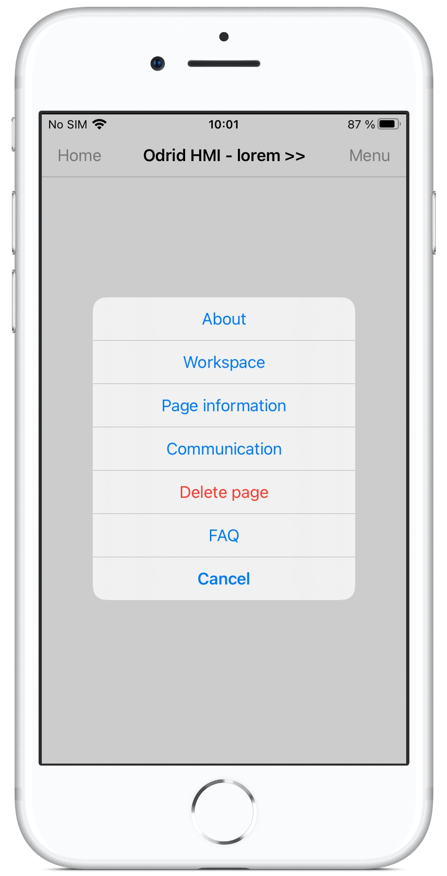
Menu
The menu contains the main commands in HMI Droid (Odrid HMI).On some Android-devices there is a dedicated menu button. On other devices, click on the three dots in the Action Bar to open the menu.
|
|
The FAQ menu item is available in Odrid HMI 1.7.6 (beta) and later and in HMI Droid 6.7.8.129 (beta) and later.
Note: There is no Import file command in Odrid HMI for iOS/iPadOS/macOS. Please see the topic Transfer files to an iOS device.
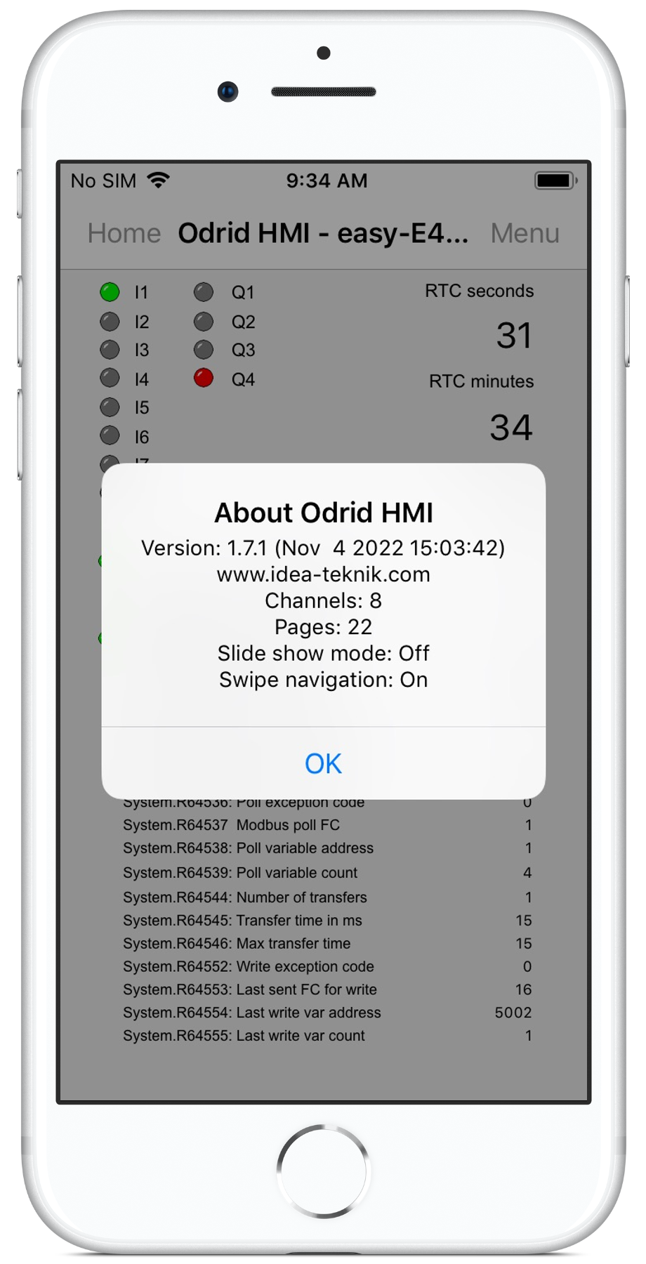
About
The about command displays a dialog with version information, number of channels and number of loaded panels (pages).The dialog also displays if Slide show mode is enabled and if navigation between panels (pages) with the Swipe gesture is enabled.
|
|
|
Workspace
The workspace is the area on the screen where the different objects are located.When creating new panels (pages) you must first find out how large the panel (page) should be. Use the command Workspace in the menu in HMI Droid (Odrid HMI) to find out the size of the workspace on your target device.
 |

|
Note: Version 1.6.2 and later of HMI Droid (Android) has support for hiding the Action Bar and System Bar providing larger workspaces.
Before there are any panels in the device the workspace has no given orientation. You can therefore find out the size of the workspace in both portrait and landscape.
The orientation is determined by how you set the width and height and is always locked to either portrait or landscape. If you enter a width greater than the height the orientation will be landscape. If you enter a height greater than the width the orientation will be portrait.
Note: HMI Droid 1.7.8.89 and later supports screen rotation and panels (pages) with mixed orientations.
Sample sizes of workspaces
| Type | Brand/model | Screen | Landscape | Portrait |
|---|---|---|---|---|
| Media player | MiniX Neo X5 | 1280 x 720 px | 1280 x 664 dp | 720 x 1224 dp |
| 11.6" Chromebook | Acer R11 (fullscreen) | 1366 x 768 px | 1366 x 633 dp | N/A |
| 11.6" Chromebook | Acer R11 (window mode) | 1366 x 768 px | 960 x 512 dp | 600 x 633 dp |
| 10.5" tablet | Samsung Galaxy Tab S4 | 2560 x 1600 px | 1137 x 535 dp | 711 x 1001 dp |
| 10" tablet | Samsung Galaxy Tab 4 | 1280 x 800 px | 1280 x 719 dp | 800 x 1199 dp |
| 10" tablet | Samsung GT-P7500 | 1280 x 800 px | 1280 x 696 dp | 800 x 1176 dp |
| 9.7" tablet | Apple iPad (iOS < 12) | 1024 x 768 px | 1024 x 704 dp | 768 x 960 dp |
| 9.7" tablet | Apple iPad (iOS 12) | 1024 x 768 px | 1024 x 698 dp | 768 x 954 dp |
| 8" tablet | Samsung Galaxy Tab Active | 1280 x 800 px | 961 x 519 dp | 600 x 879 dp |
| 7" tablet | Samsung SM-T211 | 600 x 1024 px | 1024 x 519 dp | 600 x 943 dp |
| 7" screen | Raspberry Pi | 800 x 480 px | 600 x 240 dp | 360 x 480 dp |
| 5" phone | Sony Ericsson XPERIA LT18i | 480 x 854 px | 569 x 246 dp | 320 x 496 dp |
| 5" phone | LG Nexus 5 | 1080 x 1920 px | 598 x 295 dp | 360 x 519 dp |
| 5" phone | Sony Xperia Z2 | 1080 x 1920 px | 640 x 319 dp | 360 x 519 dp |
| 4" phone | Apple iPhone 5s | 640 x 1136 px | 568 x 256 dp | 320 x 504 dp |
| 4" phone | Smart-Ex® 01 | 480 x 800 px | 696 x 246 dp | 320 x 800 dp |
Configure HMI Droid
Use the command Settings in the menu to configure HMI Droid. Specify the connection type to use, IP or MAC address, port number, communication protocol and e.g. Modbus Device ID.These parameters can also be specified per panel (page) in the communication parameters dialog in HMI Droid Studio and in that case will override the values specified in the Android or iOS device.
The settings are divided into the following categories.
Note: To access the settings on an iOS-device, press the Home button, then press the Settings icon, scroll down the list and select Odrid HMI.
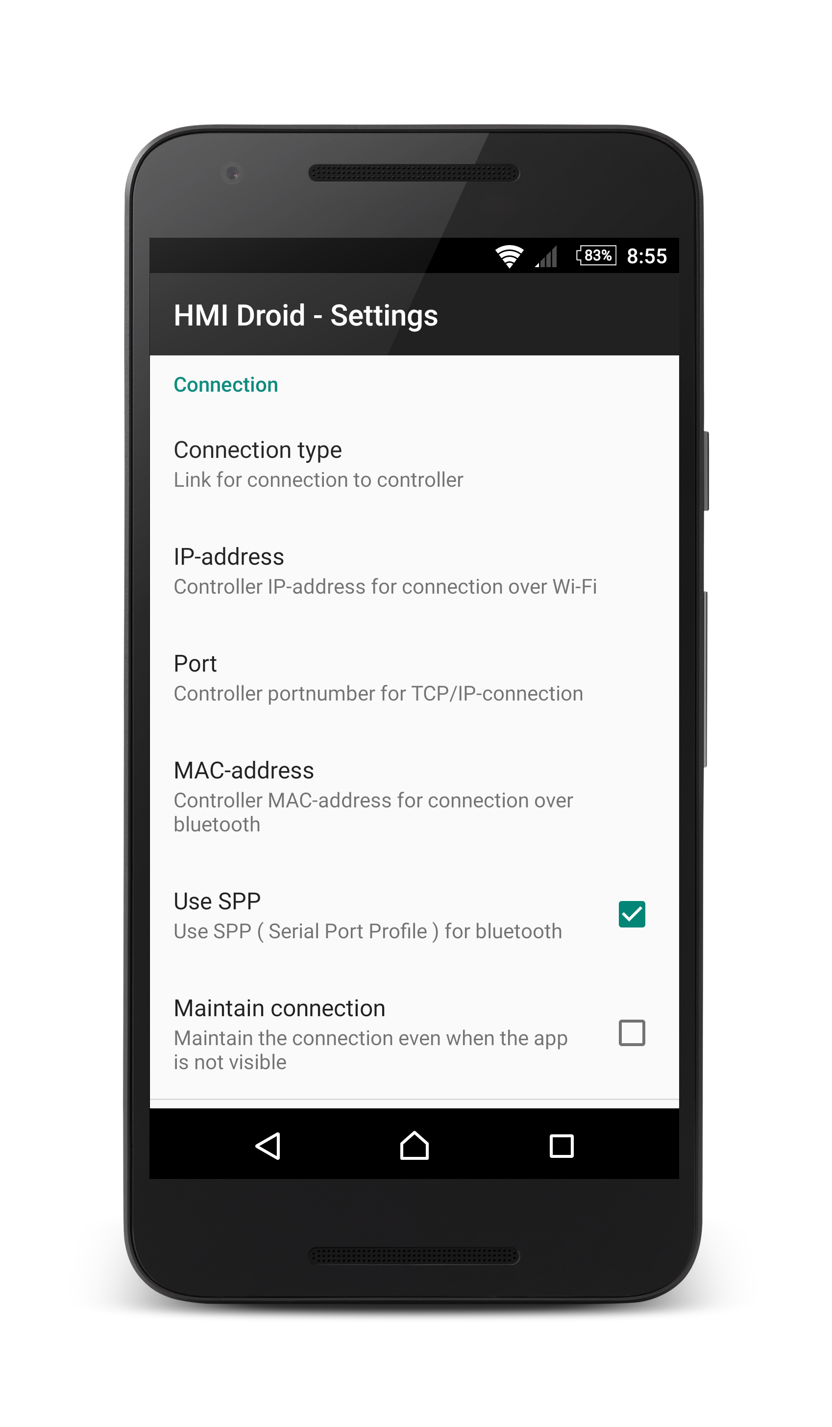
Connection settings
|
Select Connection type for the connection. Possible choices are Wi-Fi (TCP/IP), Ethernet UDP (UDP/IP) and Bluetooth. IP address. Enter the controller's IP address or host name on Wi-Fi or (mobile) internet. Port. Enter the controller's port number on TCP/IP or UDP/IP over Wi-Fi or (mobile) internet. MAC address. Enter the controller's MAC address on Bluetooth. The hexadecimal MAC address must be in all caps (upper case). Bytes must be separated by a colon. Example: 12:34:56:AB:CD:EF Use SPP. Must be ticked if SPP (Serial Port Profile) is to be used for Bluetooth. Maintain connection. Select this option if the connection to remain connected even when HMI Droid is not visible on the screen. |
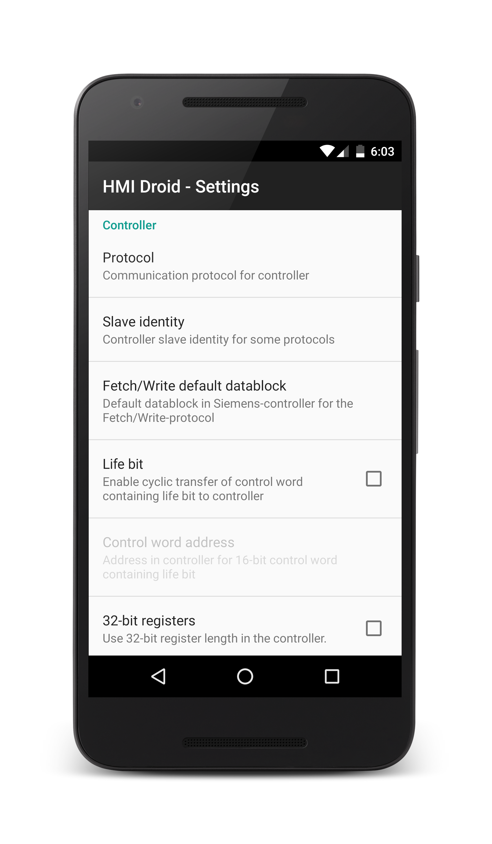
Settings for controller
|
Select the protocol. Alternatives are COMLI,
Modbus/TCP,
Modbus/TCP Class 1,
Modbus RTU Class 1,
SattBus COMLI,
Siemens Fetch/Write and
Simens S7 Communication (ISO on TCP). A Device ID between 0 and 255 must be specified if COMLI, Modbus/TCP or Modbus RTU is used. Default data block specifies which data block to use when Siemens Fetch/Write if the data block is not entered for each object. Life bit. Activate the life bit if the controller need to monitor that the communication between the Droid HMI app and the PLC/controller works. Address for control word specified as octal bit addresses to 16-bit control word. 32-bit register must be selected if HMI Droid is used with RievTech/xLogic PLCs. Select Word Swap for systems using "reversed" word order for 32 bit variables with the Modbus protocol. Poll interval is the minimum time between two polls and can be set to save battery and network traffic. Response timeout in ms. Used by the Modbus protocols. Default value is 3000. Rack for Siemens S7 controllers. Default value is 0. Slot for Siemens S7 controllers. Default value is 2. Last S7 Datablock for Siemens S7 controllers. For best performance, do not use a higher value than required. Default value is 255. This setting is available in HMI Droid 1.7.7.85 and Odrid HMI 1.2.29 or later. Modbus max block size is the maximum number of Modbus registers that will be read using one request message. Valid range is [1,125] and the default value is 55. Modbus polling optimizer is on by default and will improve the performance but must be disabled for some Modbus devices. Use Modbus FC06 makes the Modbus/TCP Class 1 protocol driver to use FC06 (Write single register) instead of FC16 (Write multiple registers) when writing 16 bit integer values. Always read full bytes is on by default and will improve the performance but must be disabled for some Modbus devices. Disconnect on rx timeout is on by default but can be disabled for Modbus RTU. Available in HMI Droid 1.7.8.120 (beta) and in Odrid HMI 1.7.6 (beta). |
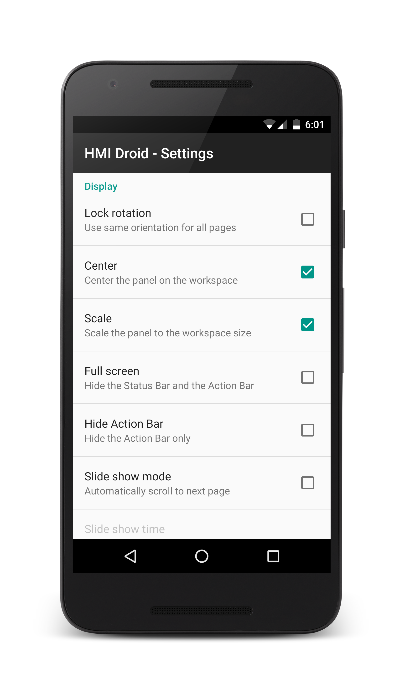
Settings for display
Lock rotation. When enabled all panels (pages) will have the same oriention as the start panel (page).Center. Tick to center the panel in the workspace. This can be used if you want to use a panel that is made for the width 320 dp on a phone with a work at a slightly greater width, e.g. 360 dp.
Scale. Tick to scale the panel to make it fit into the workspace. this can be used if you wish to use a panel that is made for the width 320 dp on a phone and run it on a tablet or vice versa.
Center and scale can be used together or separately.
Changes to these settings will not be visible until you either restart the HMI Droid or scroll multiple pages.
If scaling and/or centering is used, the device must held in the "right direction" when the app is started for it to work properly.
Full screen. Makes the workspace larger by hiding both the Status Bar and the Action Bar. Available in HMI Droid 1.6.2 and later. If the device does not have a dedicated menu button, the menu can be opened by pressing an empty area in the panel (page) for 3 seconds. In version 1.7.6.80 and later, it's also possible to use a Button with the Open options menu action.
Hide Action Bar. Makes the workspace larger by hiding just the Action Bar. Available in HMI Droid 1.6.2 and later. If the device does not have a dedicated menu button, the menu can be opened by pressing an empty area in the panel for 3 seconds. In version 1.7.6.80 and later, it's also possible to use a Button with the Open options menu action.
The app must be restarted after changing Full Screen or Hide Action Bar when scaling or centering is used.
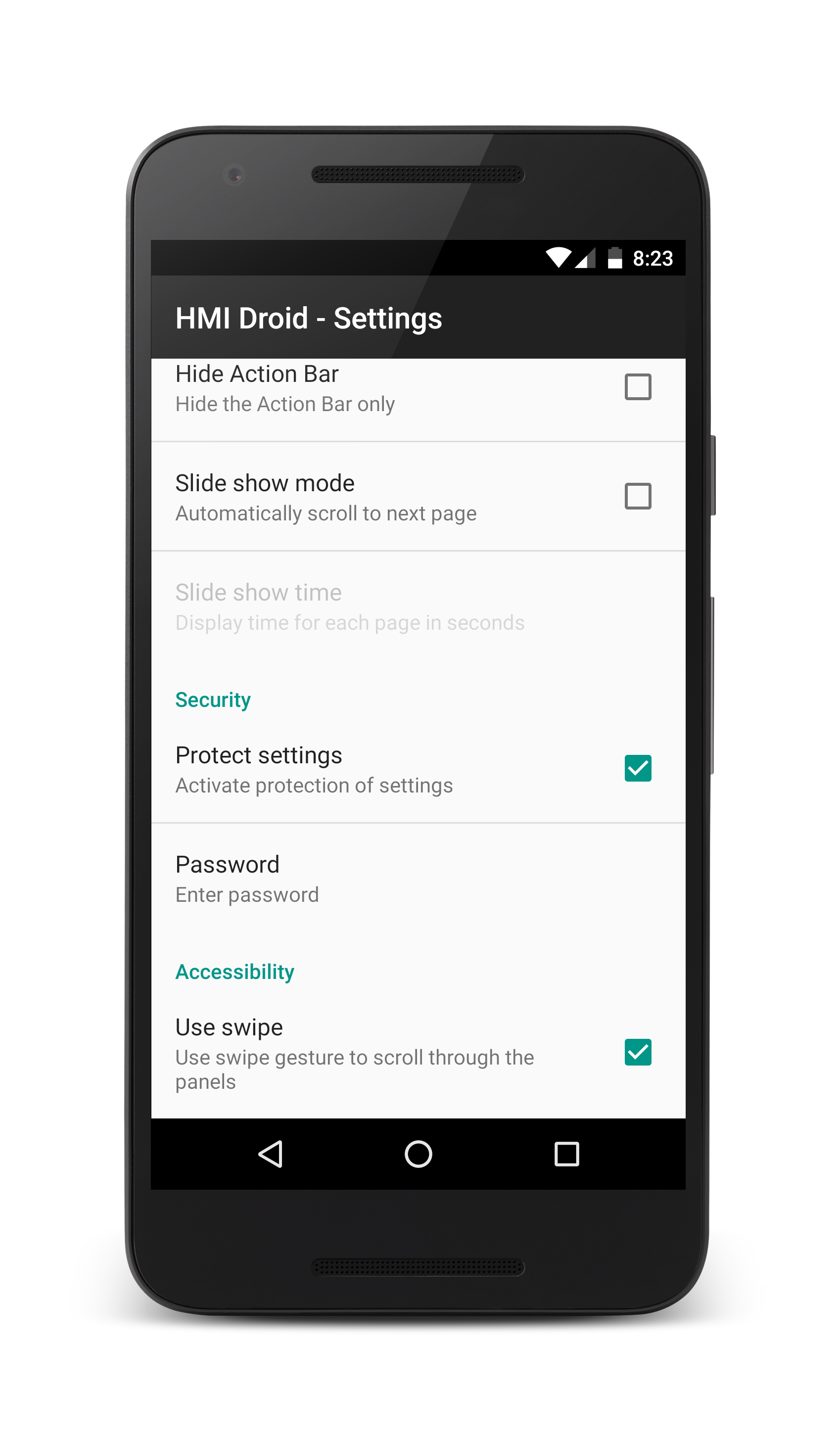
Slide show mode. Automatically scrolls to the next panel (page) after some time of inactivity. After the last page (panel) is displayed, HMI Droid will scroll back to the first panel (page). The Slide show mode overrides the Return to start panel function. Available in HMI Droid 1.7.8.95 and later.
Theme. In the iOS version of the app it's possible to change the color for the Navigation bar to dark instead of light gray.
|
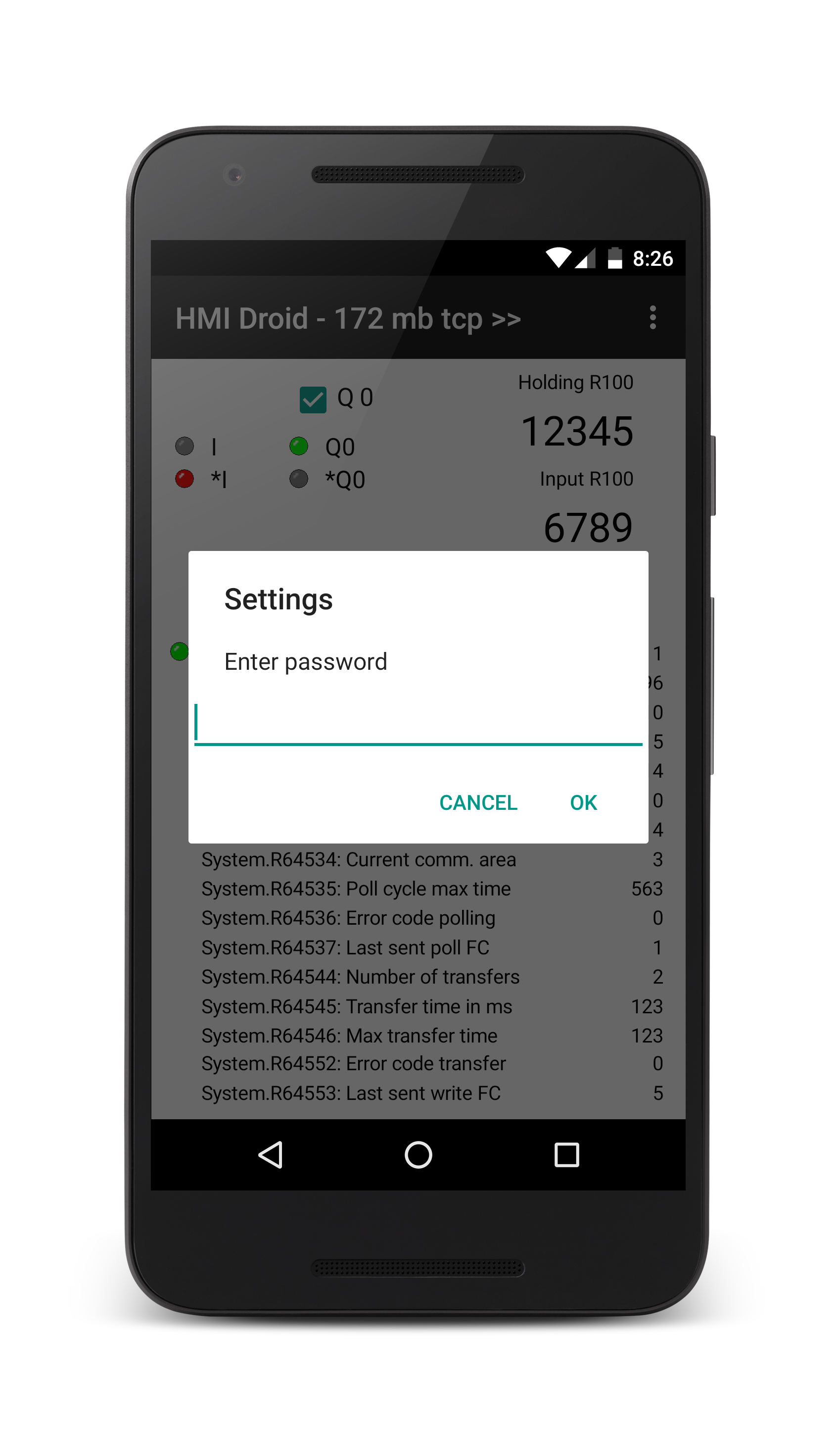
Settings for Security
You can protect the settings against accidental or unauthorized modification by requiring a password must be entered to access them.Note: This feature is not available in the iOS version of the app.
|
|
Settings för accessibility
You can turn off the scrolling between different panels using swipe if you only want to be able to navigate by pressing Buttons.The command for deleting panels (pages) can be disabled. This protects files from being deleted by mistake.
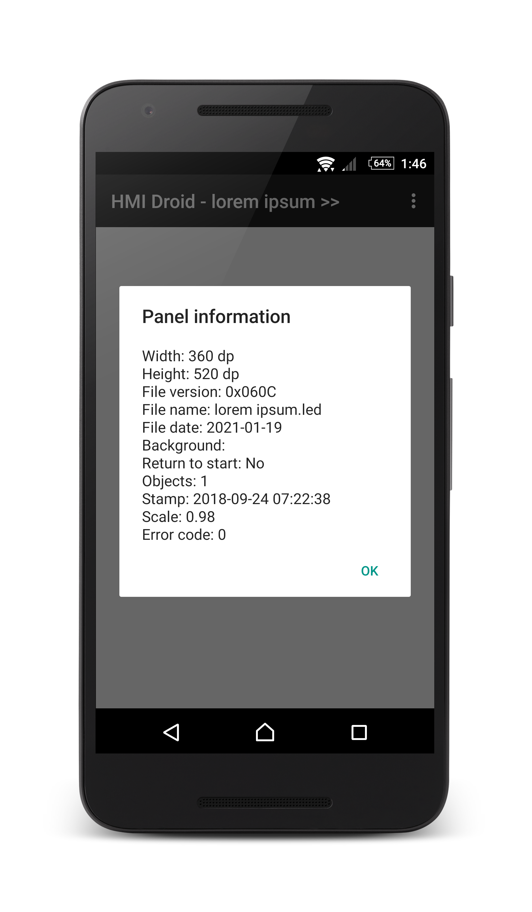
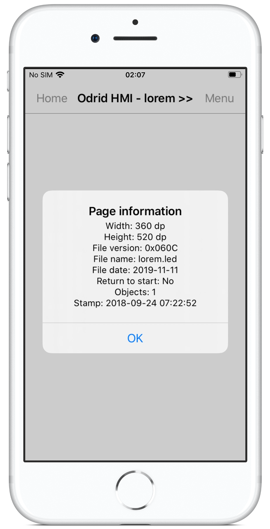
Panel information
The command Panel information shows different properties for the current panel (page) file.Stamp refers to the date and time when the panel (page) file was last saved in HMI Droid Studio. This feature can be used to verify that the correct version of the file is installed in the Android or iOS-device. Use the Information command in the File menu in HMI Droid Studio to show the stamp and compare with the stamp in the target device.
NOTE: The stamp information is available in panel (page) files edited with HMI Droid Studio 6.7.4 or later.
In HMI Droid 1.7.8.99, the current scale factor and any runtime errors are displayed.
The error codes can be ORed, i.e. more than one bit can be set simultaneously.
xxx1xx | An image Button object is missing one or more image files. | |
xx1xxx | An Image object is missing the image file. | |
x1xxxx | The Background image file for the panel (page) is missing. | |
1xxxxx | A text list file is missing (or can not be loaded) for a Numeric variable object that uses the As text format. |
|
|
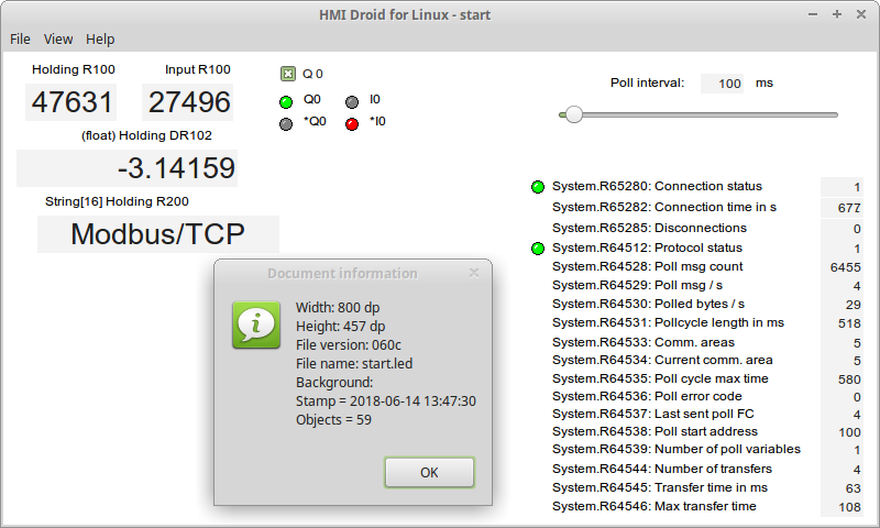
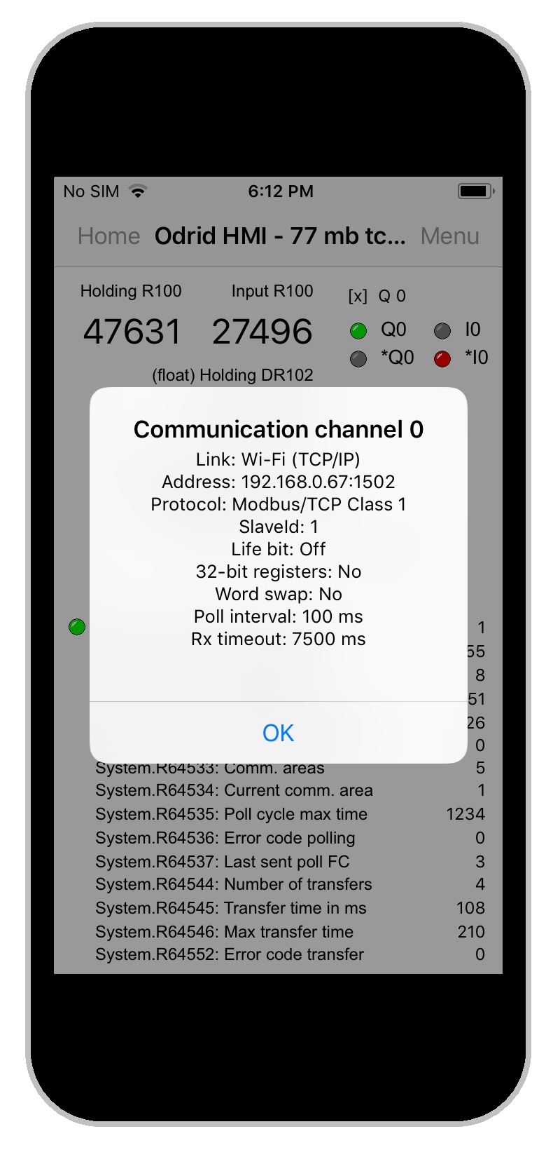
Communication diagnostics
The command Communication displays the current values for the most important communication parameters in a dialog.NOTE: In Odrid HMI (iOS) with version lower than 1.0.20, the dialog displays the initial value of Device ID for the current panel and is not affected when writing to system variable System.R64518 to change the value.
NOTE: The Poll interval parameter is displayed as "0 ms" until a connection is established with the controller.

|

|
|
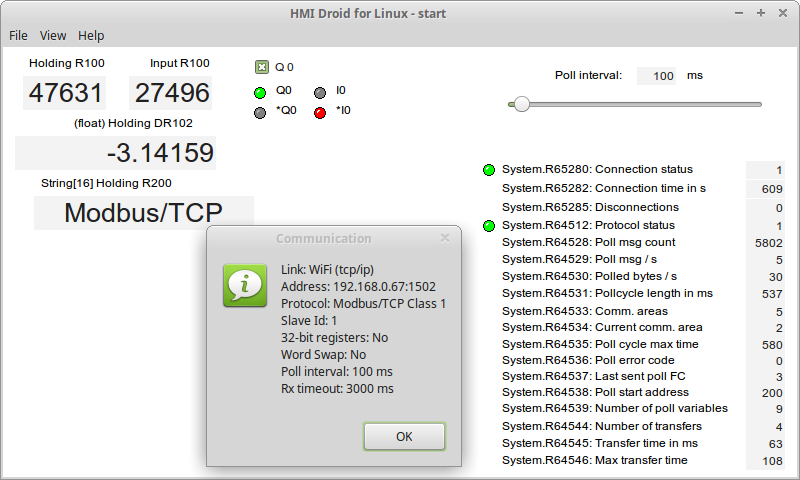
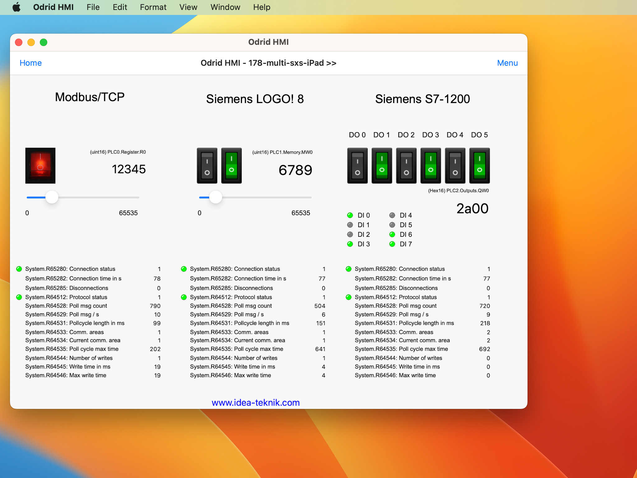
The example panel (page) 172 mb tcp 360 in the screenshots above is available for download.
172 mb tcp 360.led
Download the file and open it in HMI Droid Studio.
Modify the IP-address in the communication parameters settings to match your PLC/controller.
Use the Test run feature or transfer the file to the Android-device.
This panel (page) is 360 dp wide. On some devices the panel scaling feature therefore must be enabled to fit the workspace.
Note: This sample panel (page) uses all Modbus data types. The panel can be used with many PLCs without modifications but you may need to change addresses and/or variable areas to use it with your PLC/Controller/Gateway/Frequency converter etc.
Import file
NOTE: In HMI Droid 1.7.8.105 and later, the system file picker is used to select the file to import..
|
|
|
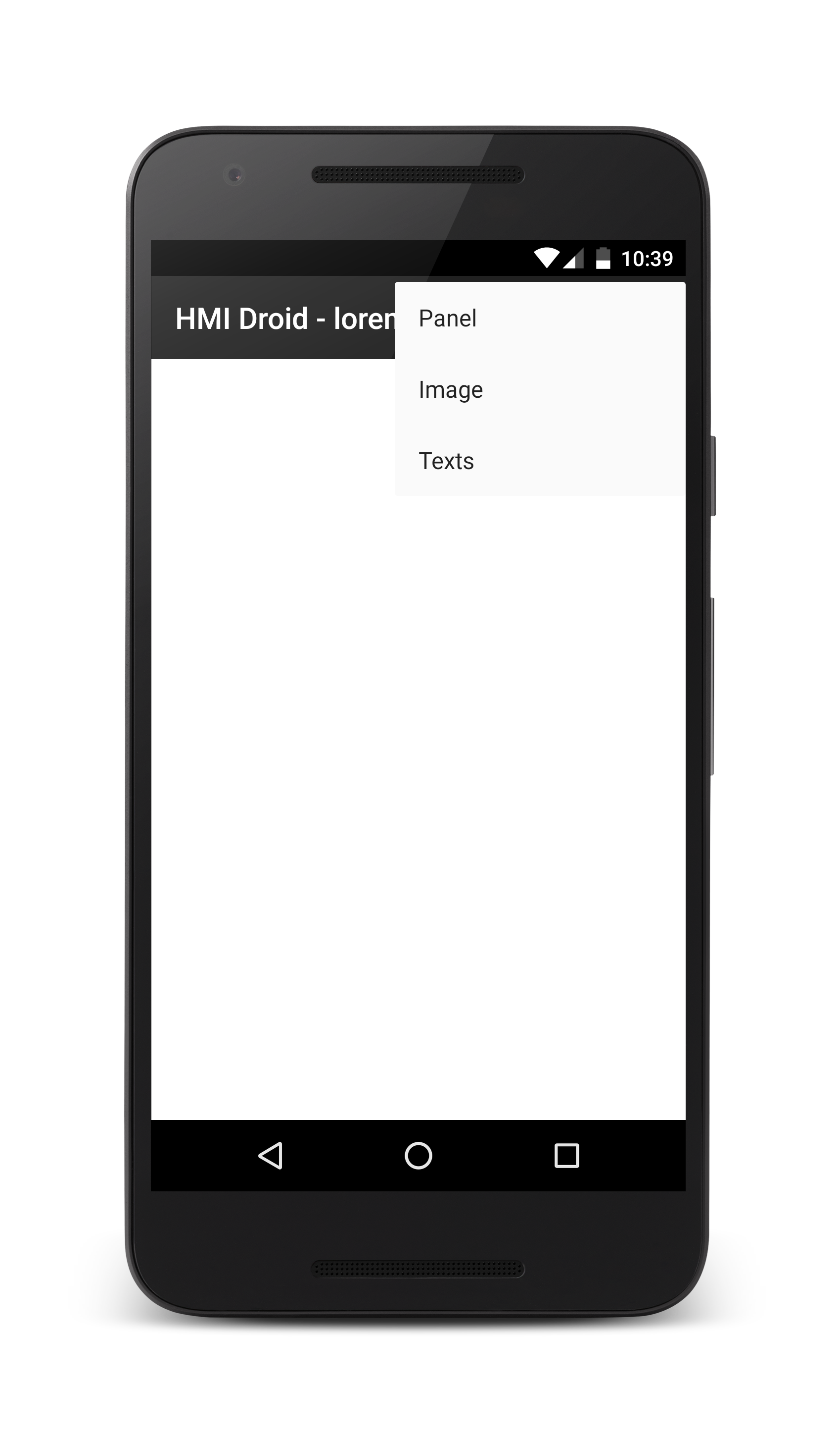
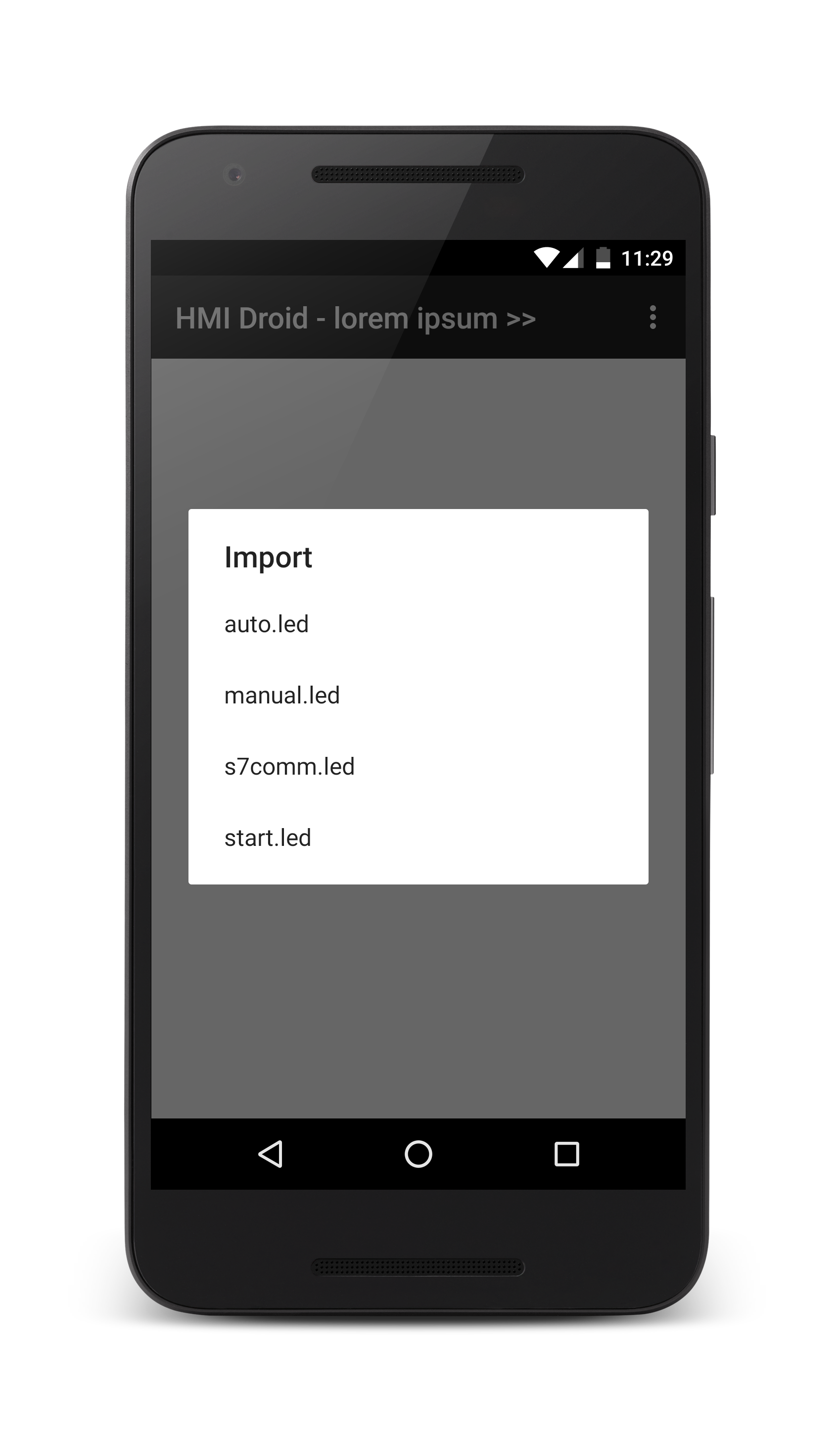
Importing content in HMI Droid 1.7.8.102 and earlier.
The import command in the Android version of the app is used for importing panel (page) files, images or text lists from the download folder on the Android device and into the work directory for the app.
First select what kind of file to import.
|
|
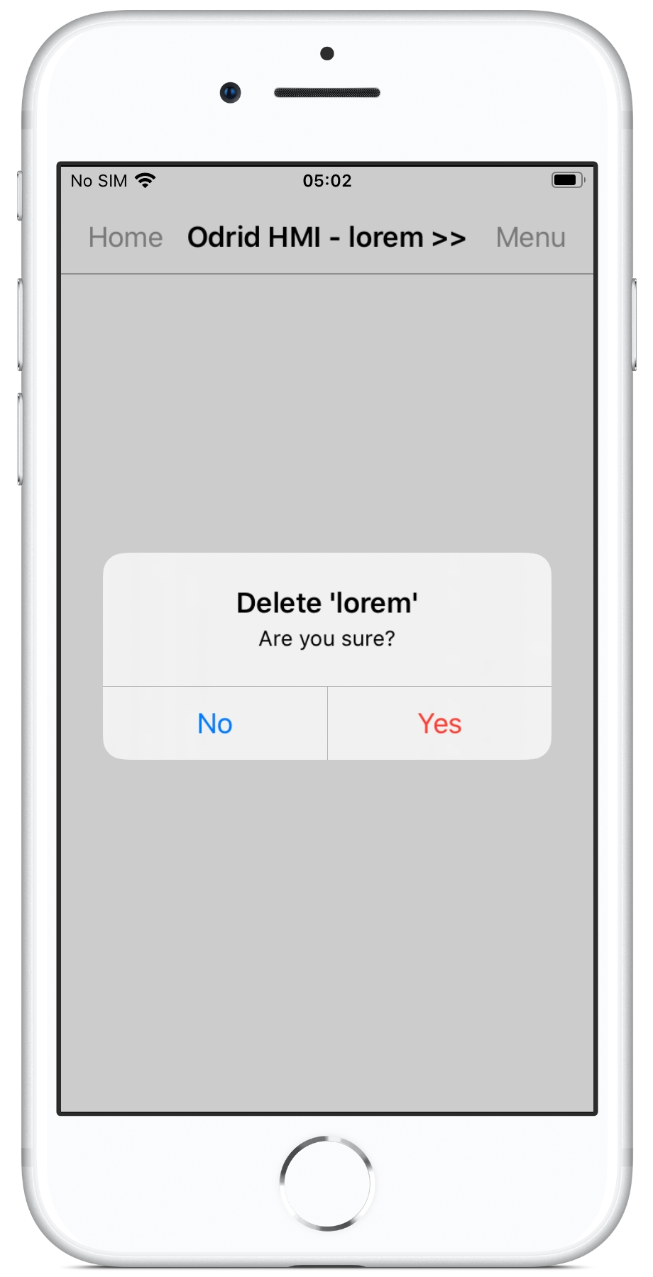
Delete
The delete command is used for deleting the current panel (page) file from the work directory on the target device.Note: Be careful when using the delete command. Deleted files can not be recovered, they have to be transferred from the PC again.
In HMI Droid 1.7.8.99 and Odrid HMI 1.0.25 or later, the delete command can be disabled in the Accessibilty section in the Settings.

|
|
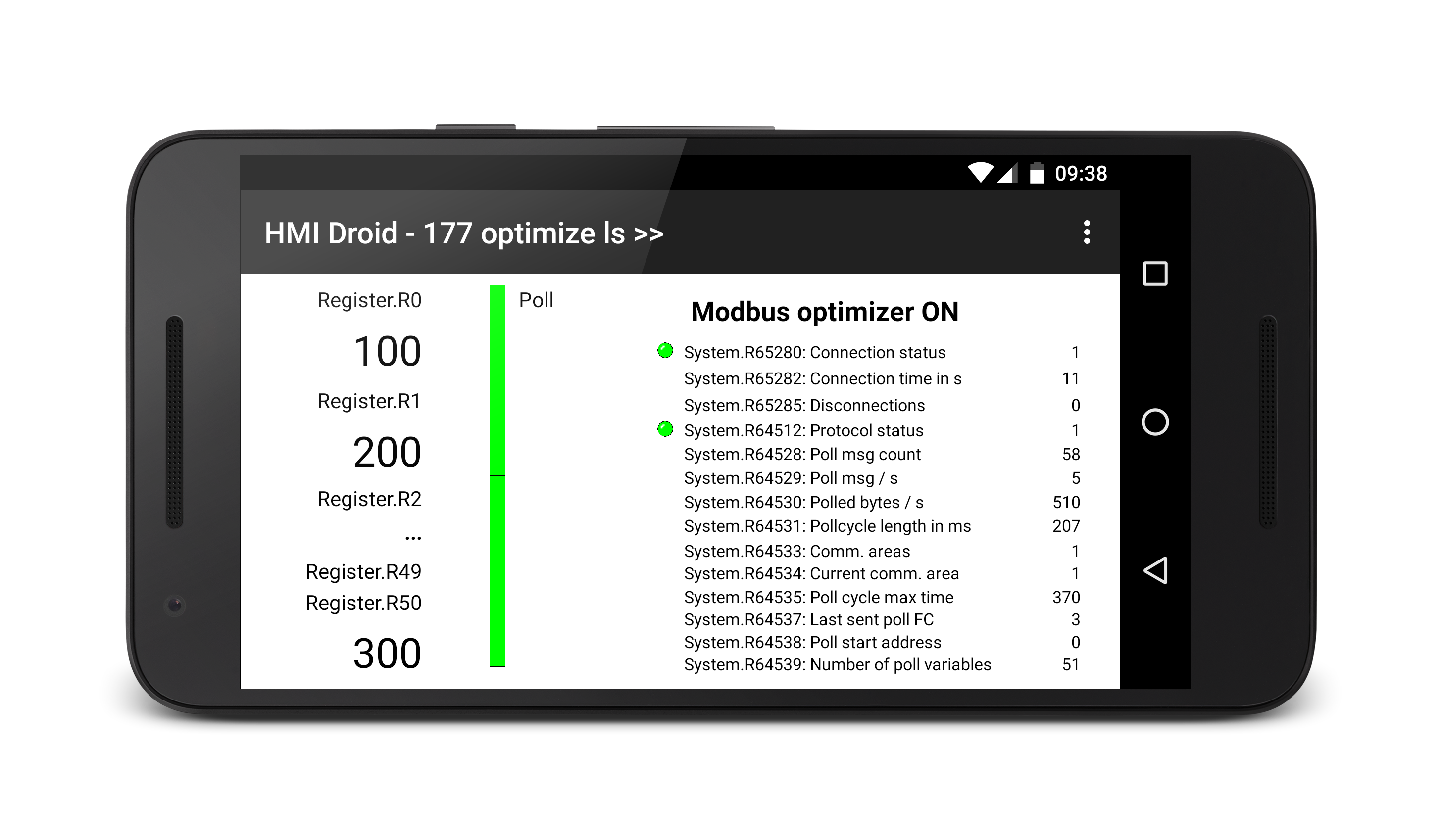
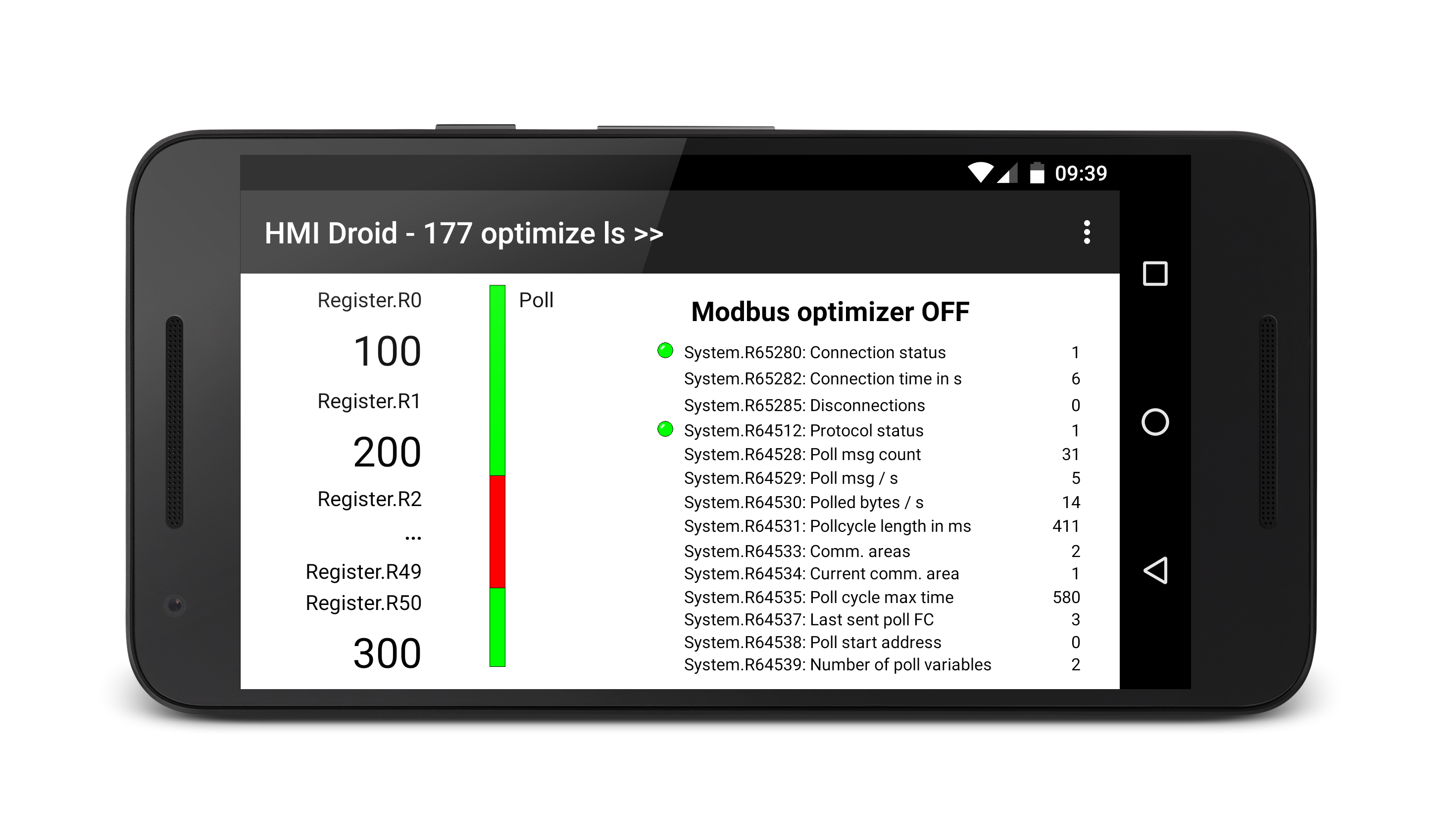
Polling optimizer
The polling mechanism in HMI Droid/Odrid HMI contains an optimizer that reads large blocks of nearby variables to improve the polling efficiency. The optimizer works fine with most standard PLCs but can cause problems with some devices:- PLCs/controllers that only supports reading a small number of Modbus Holding registers or Input registers in a single Request/Response cycle.
- Devices that have gaps in the Modbus variable map and does not support reading variables across these gaps. Example: The Schneider Electric gateway SR3NET01BD.
Note: In HMI Droid Studio 6.7.8.3101 the polling optimizer can be disabled in the Device settings.
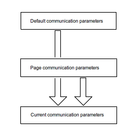
Communication parameters
The communication parameters controls how HMI Droid connects and communicates with the PLCs or other type of of controllers/devices.There are three sets/levels of communication parameters.
Default communication parameters
This set can be specified in the settings on the Android and iOS target devices and the values are used as default values for all panels (pages) and channels.Panel (page) communication parameters
This set can be specified in the communication parameters dialog in HMI Droid Studio for the panel (page) and for the different channels.The current communication parameters
This set is created when navigating to a certain panel (page). The panel (page) communication parameters will override any default communication parameters.In this set, some of the communication parameters for each channel, e.g. Modbus Device ID, can be temporarily modified at run time with different objects connected to the system registers.
Windows version (Alpha)
The Windows version of HMI Droid, currently in alpha state, can be downloaded free-of-charge by users who have purchased the Android or the iOS version of the app. Please contact us for more info.
Prerequisites and limitations:
- All panels (page) files must be stored in the folder "C:\Users\Public\Documents\HMI Droid\".
- All image files and text lists must be stored in the same folder as HMIDroid.exe is launched from.
- All settings for communication must be stored in the panels (pages).
- Navigation between panels (pages) can only be done with Buttons or Links.
Images does not support transparency.
HMI Droid (win32) 6.7.8.3132 (Alpha-version 2004-07-04)
What's new in HMI Droid (win32) 6.7.8.3132 (Alpha 2024-07-16)
- Bugfix in the script compiler for issue with multiple directives
like e.g.
$registerOffsetand$alignnot being recognized.
HMI Droid (win32) 6.7.8.3131 (Alpha-version 2004-07-04)
What's new in HMI Droid (win32) 6.7.8.3131 (Alpha 2024-07-04)
- Minor improvements.
HMI Droid (win32) 6.7.8.3130 (Alpha-version 2004-06-24)
What's new in HMI Droid (win32) 6.7.8.3130 (Alpha 2024-06-24)
- Support for scripts.
HMI Droid (win32) 6.7.8.3125 (Alpha-version 2004-04-25)
What's new in HMI Droid (win32) 6.7.8.3125 (Alpha 2024-04-25)
- Bugfix for problem with reading variables of data type Coils using Modbus/TCP when option Read full bytes is enabled.
- Bugfix for the As text format with 32-bit integer values greater than 65535.
- Bugfix for Numeric variables with the As text format using the Double register/DWORD option.
- Bugfix for Numeric variables with the PHYS format using the Double register/DWORD option.
- Bugfix in the Line Graph object for the Sampling interval in the Logging mode.
- Bugfix/improvement in the protocol driver for Siemens S7 Communication (ISO-on-TCP)
HMI Droid (win32) 6.7.8.3121 (Alpha-version 2023-12-28)
What's new in HMI Droid (win32) 6.7.8.3121 (Alpha 2023-12-28)
- Transparent backgrounds in images for Image objects and Buttons are displayed correctly.
- Bug fixes.
HMI Droid (win32) 6.7.8.3120 (Alpha-version 2023-12-26)
What's new in HMI Droid (win32) 6.7.8.3120 (Alpha 2023-12-26)
- Three (3) error messages for Siemens S7 String errors.
- New option Read full bytes in the Device settings for Modbus Coils and Discrete Inputs.
- New option Disconnect on timeout in the Device settings for the Modbus RTU protocol.
- Support for using multiple Device ID in the same channel when using the Modbus RTU protocol.
- Support for the system registers for enable and online per Device ID when using the Modbus RTU protocol.
- Improved error handling/reporting.
- Two old DLLs have been removed.
- Bug fixes.
HMI Droid (win32) 6.7.8.3118 (Alpha-version 2023-03-21)
What's new in HMI Droid (win32) 6.7.8.3118 (Alpha 2023-03-21)
- Accelerated navigation between panels (pages).
- Bug fixes.
HMI Droid (win32) 6.7.8.3112 (Alpha-version 2022-12-19)
What's new in HMI Droid (win32) 6.7.8.3112 (Alpha 2022-12-19)
- New command
File|Open...for navigating to arbitrary panels (pages). - Faster launch.
- Minor bugfixes.
HMI Droid (win32) 6.7.8.3112 (Alpha-version 2022-12-09)
What's new in HMI Droid (win32) 6.7.8.3112 (Alpha)
- Support for up to eight concurrent channels.
- Connection type Bluetooth SPP.
Odrid HMI for macOS
Prerequisites: macOS 10.15 or later.
Use the Finder to move your files (*.led, *.png and *.txt) to the
~/Library/Containers/se.ideautomation.Odrid-HMI/Data/Documents folder before launching the Odrid HMI app.In Odrid HMI 1.6.8 (beta) and later, content can be imported by double clicking the *.led-file or by using the "Open with..." command.
This version of the app uses the iPad idiom which will scale down the main window of the app to 77%.
The swipe gesture for browsing between panels (pages) on iOS devices can be emulated with a two finger swipe on the trackpad.
Windows Subsystem for Android
Important: Because Microsoft is ending support for the Windows Subsystem for Android (WSA), Amazon Appstore on Windows 11 will no longer be supported after March 5, 2025.Windows Subsystem for Android (WSA) enables your Windows 11 device to run HMI Droid installed from the Amazon App Store.

Note: Copying content from the file system on the Window 11 device and to the file system in Windows Subsystem for Android is not as simple as with an Android device. There are different ways to perform this and we suggest using Android Debug Bridge (adb) for transferring the files (*.led, *.png and *.txt) from Windows to the Download folder in Windows Subsystem for Android and then importing the files one by one into HMI Droid with the Import command.
Example:
adb push <filename> /storage/emulated/0/Download/Developer mode in the settings for Windows Subsystem for Android must be on to connect Android Debug Bridge to Windows Subsystem for Android.
Advanced networking in the settings for Windows Subsystem for Android must be on to connect to a device on the same same network.
Note: There is currently no support for Bluetooth in Windows Subsystem for Android.
Create and edit panels (pages)
The panels (pages) for HMI Droid / Odrid HMI are created and edited with HMI Droid Studio.This tool, available free-of-charge, is used on Windows PCs and each panel (paged) is saved as a separate file.
The pages are then transferred to the work folder for the app on the Android or iOS/iPadOS device using a suitable method for Android or iOS/iPadOS.
Any images and text files used to display a variable as a text must also be transferred to the work folder for the app on the Android or iOS/iPadOS device.
Transfer files to an Android device
How to transfer content for HMI Droid (*.led, *.png and *.txt-files) to the work folder for the app.Recommended methods:
1. Import command
Use the Import command to transfer the files from the Download folder on the Android device or from Google Drive. Restart HMI Droid to load the file.2. File explorer on PC
Connect the Android device to the Windows PC with a USB-cable and then use a file explorer to transfer the files to theAndroid/data/se.ideautomation.hmidroid/files folder on the Android device. Restart HMI Droid to load the file.3. File explorer on Android device
In older versions of Android, it's possible to transfer the files to the work folder for HMI Droid using a file explorer on the Android device. However, in Android 11 or later this is no longer possible.Transfer files to an iOS device
How to transfer content for Odrid HMI (*.led, *.png and *.txt-files) to the work folder for the app.Recommended methods:
1. E-mail attachment
Send the file as an email attachment and then open the file on the iOS device in Odrid HMI. Transferring images with this method includes an extra step since the image will first be opened in the Quick Look app and then has to be sent to Odrid HMI using the share button.2. iCloud
Upload the file to iCloud and then use the Files app on the iPhone or iPad to open the file in Odrid HMI. Restart Odrid HMI to load the file.3. iTunes
Use Apple's iTunes App on a Windows PC to transfer the files to the iPhone or iPad connected with a USB-cable. Restart Odrid HMI to load the file.4. macOS Finder
Use the Finder app on a Mac with macOS 10.15 or later to transfer the files to the iPhone or iPad connected with a USB-cable. Restart Odrid HMI to load the file.There are other methods too like using e.g. Dropbox.
Download HMI Droid Studio
The development tool HMI Droid Studio is available in two versions. A free-of-charge version can be downloaded here. This version does not require any installation, just extract the zip file and then start HMIDroidStudio.exe. Do not rename or delete any of the extracted files.HMI Droid Studio can also be downloaded from the Micosoft Store at a low cost. This version does not have the 15 minutes time limit for the panel (page) test run feature.
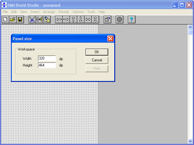
Using the HMI Droid Studio
When starting the HMI Droid Studio a blank panel (page) is displayed. Use the Panel size command in the Format menu to make the panel (page) the same size as the workspace on your target device. If the size of the panel (page) does not match the workspace, the panel (page) will either be cropped or not fill the entire workspace when displayed on the device unless scaling is enabled.Save the first panel (page) as start.led which is the name of the panel (page) to be displayed when starting the HMI Droid.
When saving a panel, a backup of the old file is created with the same name but with .~le as file extension.
If you will have many panels (pages) it may be advisable to put some buttons for navigation, especially in the first panel, so you do not have to browse so far.
File versions
Implementing new features in HMI Droid (Odrid HMI) sometimes requires changes to the *.led-file format and the file version is therefore incremented when major updates of HMI Droid Studio are released.The *.led-files used for the panels (pages) are always backward compatible but you can not use *.led-files created in a new version of the development tool with an old version of the app.
Minimum app versions required to open a panel (page) *.led-file of a particular file version:
| File version | Introduced | HMI Droid Studio | HMI Droid | Odrid HMI | Examples of new features |
|---|---|---|---|---|---|
| 0x060D | 2018-10-15 | 6.7.8.3076 | 1.7.8.88 | 1.3.0 | Channels |
| 0x060C | 2018-02-20 | 6.7.7.2064 | 1.7.7.85 | 1.2.29 | More than 255 S7 Datablocks |
| 0x060B | 2018-01-13 | 6.7.6.1060 | 1.7.6.80 | 1.1.26 | Animated image buttons |
| 0x060A | 2016-04-27 | 6.7.5.37 | 1.7.5.70 | 1.0.10 | New variable area Objects |
| 0x0609 | 2016-03-15 | 6.7.4.34 | 1.7.4 | 1.0.3 | Improved number formatting |
| 0x0608 | 2015-10-05 | 6.7.1 | 1.7.1 | 1.0.0 | New format: TIME_OF_DAY |
If the file version is too high, an error message will be displayed.

|
Naming panels (pages)
The panel (page) that is displayed when HMI Droid is launched must be named start.led. The other panels (pages) can be named arbitrarily, but the file name must be in lower case and the extension must be .led. The name must be a valid file name in both Windows and Android or iOS.NOTE: HMI Droid Studio does not support dots (.) in file names.
If you will navigate from one panel to another panel by using the buttons you have to limit the length of the filename to a maximum of eight characters. This is a legacy of LEDpanel and Windows 3.1 and will changed later on.
HMI Droid shows the panel start at the left and all other panels sorted alphabetically to the right of this panel. If you see ">>" after panel name in the app action bar (or navigation bar) it means that you can scroll to the right. If not the ">>" is appearing, you are on the last panel (page).

|

|
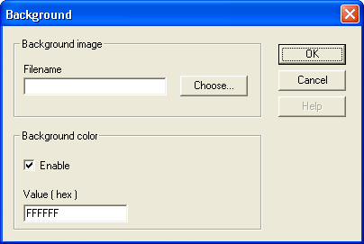
Background
Filename for optional background image must not contain a file path.Store the image files that will be used in the same directory on the PC as the panel files. Always save the panel (page) on the PC in this directory before selecting an image filename. This will make HMI Droid Studio to automatically remove the path from the image filename.
Image files must be transferred to the target device manually, they are not included in the *.led-file for the panels (pages).
Warning: The target device may run out of memory if very large images are used!
From version 1.6.4 the background color of the panel (page) can be choosen. The color value is RGB, but in the reverse byte order. Enter FFFFFF for white.
Note: The current version of HMI Droid Studio does not support alpha channel (transparency) in images. For best result, use images with the same background color as the panel (page).
Update: HMI Droid Studio 6.7.8.3121 (beta) and later supports alpha channel (transparency) in images.
See the topics Transfer files to an Android device and Transfer files to an iOS device for information about how to transfer the background image to the target device.
Panel properties
In the dialog panel properties, you can specify whether to return to the start panel (page) after a period of inactivity.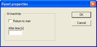
Grid
The Grid is a pattern of dots that covers the panel (page) in the development tool. Objects can be snapped to the grid when moved or resized.The settings for x and y are also used to control the number of pixels (dp) that the objects move if you hold down the Shift key when moving selected objects with the cursor keys.
The choosen color for the grid will be used for the object handles too.

Objects
The panels (pages) in HMI Droid are built up with different types of objects. A panel (page) may also contain a background image.- Light emitting diode (LED)
- Text/Label
- Time
- Date
- Button
- Numeric variable
- Input field
- Image
- Slider Bar
- Bar Indicator
- Chart / Line Graph
- Checkbox
- Radio button
- ST program block (Implementation in progress.)
- Function block (Implementation in progress.)
Update: In HMI Droid Studio 6.7.8.3093, the panel (page) is checked for overlapping Objects when the file is saved.
Upcoming scripts in HMI Droid Studio 6.7.8.3126
All GUI-Objects will support the following script properties.
| Property name | Access | Description |
|---|---|---|
| show | Read/Write | Show the Object if the condition is true (1), hide otherwise. |
Light emitting diode (LED)
LEDs can be used to view the status of boolean variables. The variables are automatically retrieved from the selected variable area in the controller/PLC.Bit address for the variables can be defined in different ways depending on which communication protocol that is used. For COMLI octal address is used. To interface with e.g. Siemens systems you can also enter the address in the format "byte number dot bit" for example, DBnn.DBX12.3, or "register number colon bit" for systems using Modbus/TCP or Modbus RTU. Selection of address format is done with a command in the Format menu.
LEDs are available in two sizes, 12x12 and 16x16 dp. Use the command LED type in the Format menu for choosing size.

|

|

|
| Property | Description |
|---|---|
| Channel | The Channel to read variables from. Feature available in HMI Droid Studio 6.7.8 and later. |
| Variable area | The variable area which the LED will read variables from. |
| Data block number | The data block the LED will read from when using the Siemens S7 Communication (ISO-on-TCP) protocol. |
| Animation | How the LED should work. If the specified variable for a certain color is true, the LED will illuminate with that color. If multiple conditions are met, the color will be determined by the condition with the highest priority. |
| Bit address | The bit address of a variable in the selected address format. |
| Invert | Inverts the signal so that the LED illuminates if the signal is low. |
| Priority | Precedence for the colors if multiple conditions are used. |
| Address format | Displays the address format which you have chosen to use. It has to correlate with the type of controller that you should connect to. |
| Show as rectangle | Displaying a rectangle instead of a round LED. |
| Use any size | Use any size and not just the 12x12 and 16x16 dp sizes e.g. for Andon systems with requirements for readability at a long distance. |
| Hide | Not implemented presently. |
| Comment / directive / script | Here you can write a comment. In HMI Droid 1.7.8.99, Odrid HMI 1.5.0 (Beta) and HMI Droid Studio 6.7.8.3099 (Beta), an offset can be used to extend the bit addresses above R4095:14 with the $registerOffset directive. Example: $registerOffset="24576";Note: The $registerOffset directive can only be used with the Modbus data types Holding Register and Input Register. |
Diagnostic dialog
In HMI Droid 1.7.8.121 (Beta) and later, a diagnostic dialog can be opened by making a long press on the LED object.

Upcoming scripts in HMI Droid Studio 6.7.8.3126
The LED object will support the following script properties.
| Property name | Access | Description |
|---|---|---|
| intValue | Read/Write | The color for the LED-object as an integer value in the range 0 to 4. |
Text/Label
Texts/Labels are typically used together with LEDs, Numeric variables, Input fields, Sliders, Bar indicators or Line charts.

|

|

|
| Property | Description | ||||||||||||||||||||||
|---|---|---|---|---|---|---|---|---|---|---|---|---|---|---|---|---|---|---|---|---|---|---|---|
| Text | The fixed text to be displayed (max. one line) | ||||||||||||||||||||||
| Alignment | Choose between left, center and right. The text maintains the position if the text or the font is changed. | ||||||||||||||||||||||
| Fit width and height | Text object's size is automatically adapted to the length of the text and the selected font. Fonts are not identical in Windows, Android and iOS. If the object is cropped or truncated on the target device you should uncheck the "Fit width and height option" and manually increase the size of the object. |
||||||||||||||||||||||
| Hide | Not implemented presently. | ||||||||||||||||||||||
| Link | Name of a panel (page) without extension or a web address that will open when you
touch the text. A web address has to begin with either http:// or https:// eg
http://www.ideautomation.se and will open in the default browser. Links are displayed
with blue underlined text. Some values for Link can be used for relative navigation between panels (pages).
The link feature is available in HMI Droid V1.7.4 and later. |
Time
Displays the current time in hh:mm:ss format.Upcoming scripts in HMI Droid Studio 6.7.8.3126
The Time object will support the following script properties.
| Property name | Access | Description |
|---|---|---|
| intValue | Read | The current time expressed in seconds. |
Date
Displays the current date in yy-MM-dd format.Button
Buttons can be used to manipulate variables and to navigate between different panels (pages).Buttons should have a minimum size of at least 48 x 48 dp on an Android-device or 44 x 44 dp on iOS-device. A gap between buttons, or other objects that uses touch, of at least 8 dp is recommended.

|

|

|
| Property | Description | ||||||||||||||||||||||||
|---|---|---|---|---|---|---|---|---|---|---|---|---|---|---|---|---|---|---|---|---|---|---|---|---|---|
| Text | Text to display on the button. | ||||||||||||||||||||||||
| Multi line text | The text should appear on multiple lines. Hard line breaks normally works better than word wrapping. | ||||||||||||||||||||||||
| Channel | The Channel to read variables from. Feature available in HMI Droid Studio 6.7.8 and later. | ||||||||||||||||||||||||
| Variable area | Variable area in the controller that is used when the button controls variables and for optional animation of the lighted button. | ||||||||||||||||||||||||
| Data block number | Data block that will be used if the variable area is Data block. | ||||||||||||||||||||||||
| Action | What should happen when you press the button. Choose from the following actions.
Other actions have presently no function in HMI Droid. |
||||||||||||||||||||||||
| Choose... | Select the file name for the action "change panel". | ||||||||||||||||||||||||
| Lighted pushbutton | Check if the button should be a lighted pushbutton i.e. if the button should illuminate when the selected condition for the animation is true. | ||||||||||||||||||||||||
| Animation | Open the dialog for configuring animation. | ||||||||||||||||||||||||
| Image button | Use images to draw the buttons different states (Normal, Pressed) instead of using a native button. This feature is available in HMI Droid 1.7.4 or later. | ||||||||||||||||||||||||
| Setup | Open the dialog for configuring the image button. | ||||||||||||||||||||||||
| Function key | Indicate whether the button should be activated with a function key. This feature is not available in the Android and iOS versions of HMI Droid. | ||||||||||||||||||||||||
| Password | Enter any password for the action "Change panel". If a panel contains buttons for navigation that is protected with a password, you can not navigate away from this panel by using a swipe gesture. | ||||||||||||||||||||||||
| Hide | Not implemented presently. | ||||||||||||||||||||||||
| Avoid read / Write only | Avoid to read variables from the controller/PLC for performing bit manipulation operations. Can be used with Modbus datatype Coil except when toggling bits. Feature available in HMI Droid Studio V 6.7.7.2064 and later. | ||||||||||||||||||||||||
| Comment / directive / script | Here you can write a comment. |
Bit addresses for boolean variables can be entered in different ways. Use the address format command in the Format menu to choose the correct format.
[1] If using the action 'Set flag (momentary)', there is a risk that the variable is not reset when releasing the button in case the communication is not stable. Therefore it's highly recommended to use the Control word with life bit feature and to monitor the bit in the PLC by using two timers. One timer for the on state and one timer for the off state of the 'Life bit'. Since the 'Life bit' changes state every second, the timers should have a preset value of e.g. 1.5 seconds.
Upcoming scripts in HMI Droid Studio 6.7.8.3126
The Button object will support the following script properties.
| Property name | Access | Description |
|---|---|---|
| enable | Write only | Enable the button if the condition is true, disable otherwise. |
Animation of lighted pushbutton
A button can be animated so it mimics a lighted pushbutton and illuminates with a certain color when a condition is true.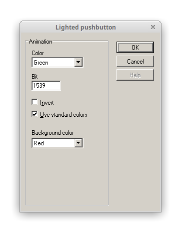
| Property | Description |
|---|---|
| Color | The color that the button should show when the boolean condition is true. |
| Bit-address | Bit-address for the boolean variable. The same variable area and datablock number are used as for the Button action. |
| Invert | Inverts the signal so that the button illuminates if the signal is low. |
| Use standard colors | Use a standard color scheme for the blue, red, yellow and lime colors. |
| Background color | Color that the button will show when the boolean condition is false. |
More colors (black, blue, cyan, gray, green, lime, magenta, maroon, navy, olive, purple, red, silver, teal, white, yellow. orange and steelblue) can be used with HMI Droid Studio V6.7.6.1060 or later.
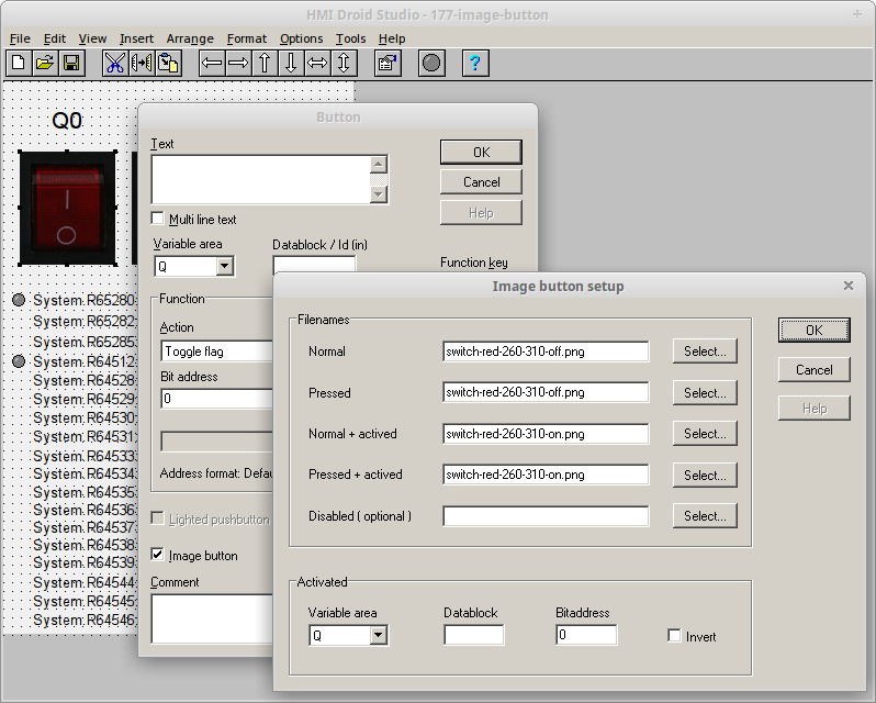
Image button setup
|
|
|
Select the image files to be used for displaying the Normal and Pressed state of the button.
The filename for the Disabled state is intended for future use. Please leave this field blank.
Image files must be stored in the same directory as the panel (page) files.
Note: Image files must be transferred to the target device manually, they are not included in the *.led-file for the panels (pages).
The images will be scaled to fit the button.
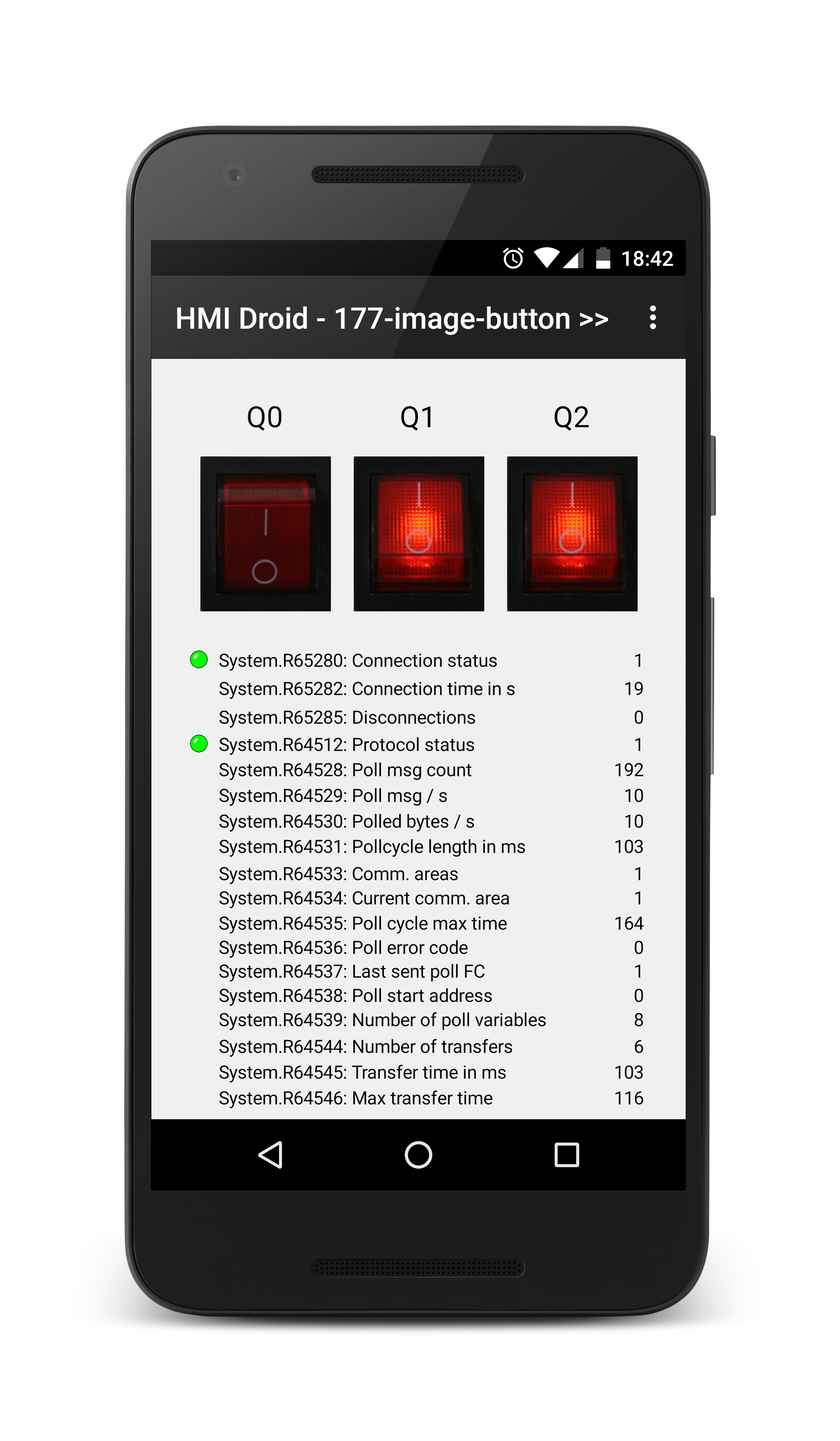
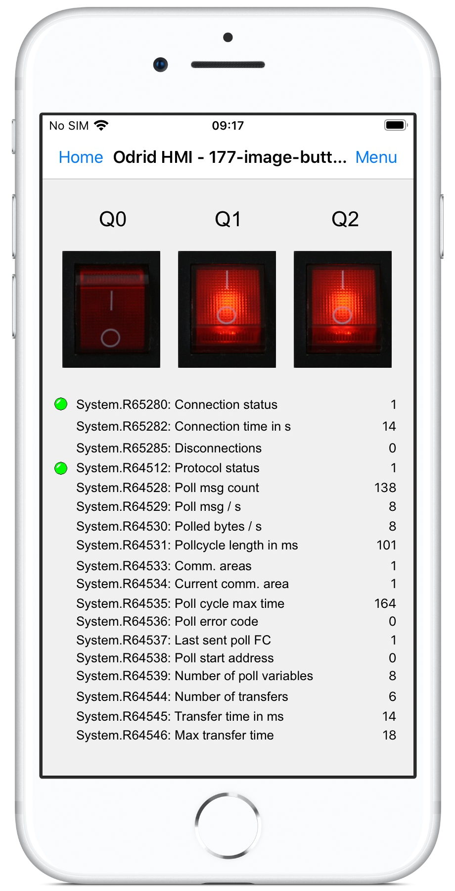
In HMI Droid Studio V 6.7.6.1060 and later, the image button can be animated.
For best Look and feel experience of an animated image button, four different images are recommended.
However, two different images can be sufficient using the same image for the pressed and not pressed states.
Note: The current version of HMI Droid Studio does not support alpha channel (transparency) in images. On some Android devices, a small rectangle will be drawn inside the image button before the image is drawn. For best result, use images with the same background color as the panel (page).
Update: HMI Droid Studio 6.7.8.3121 (beta) and later supports alpha channel (transparency) in images.
Warning: The target device may run out of memory if very large images are used!
The example panel (page) in the screenshots above is available for download.
177-image-button.led
switch-red-260-310-off.png
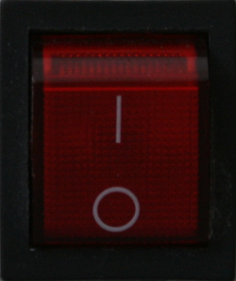
switch-red-260-310-on.png
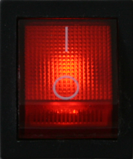
Download the files and open the *.led file in HMI Droid Studio.
Modify the IP-address in the communication parameters settings to match your PLC/controller.
Use the Test run feature or transfer the files to the Android or iOS-device.
Numeric variable (variable field)
Numeric variables (variable fields) are read from the selected variable area and displayed in the way you specify in the object's configuration dialog.If you check the box "Allow change" you can change the value online. Tap and hold the numeric variable (variable field) object to open the change value dialog.
In order to tap a numeric variable (variable field), it should be at least 48 dp high. The size is controlled by the font, a font size of at least 20 points is recommended.

|

|
| Property | Description |
|---|---|
| Channel | The Channel to read variables from. Feature available in HMI Droid Studio 6.7.8 and later. |
| Variable area | Variable area to read from. |
| Datablock / Object id (in) | Enter the number of the datablock if the selected variable area is Datablock. Object id if the variable area is Objects. |
| Address / value | Address of the variable or a 16-bit unsigned integer value when using the variable area 'Const'. Addresses are zero based and entered in decimal form. In some controllers, such as Siemens S7, byte addressing is used. |
| Double register/DWORD | Specifies that the variable is a 32-bit variable instead of 16-bit. |
| BYTE | Specifies that the variable is a 8-bit variable instead of 16-bit. Available in HMI Droid Studio 6.7.8.3098 and later. NOTE: This checkbox is currently disabled but will reflect the $typeOverride="byte"; directive in the comment. |
| Format | Controls how the variable is displayed.
|
| Settings... | Setup number formatting for hexadecimal and floating point numbers or configure the PHYS format. |
| Low byte first | Use little-endian byte order for the ASCII format. |
| Source | Name of the text file containing values and the texts to display for
each value for the format As text. Each line must begin with an unsigned decimal
value followed by a single space and then the text to be displayed. The maximum length
of the text is currently 80 characters. The text file must be a plain text file created
with e.g. Notepad. If the text file is edited, the HMI page has to be closed and
reopened to load the new content.
The name can not be longer than eight (8) characters (plus extension) and the extension must be .txt
to be able to import the text list into the Android and iOS/macOS versions of the app.
|
| Default | Text to be displayed if there is no text in the text list for a certain value. |
| Max length | The maximal number of characters in the variable of type String. For Siemens S7 Communication this setting must match the maximum length of the String variable in the PLC exactly. |
| Reversed byte order | Use little-endian byte order for the STRING format. This applies to Modbus only. |
| Allow change | Allows the variable is changed from the panel. It's only if you have ticked this box that the dialog Change value will contain a button for OK. |
| Fit width and height | Adjusts the size of the object to the current format and the selected font size. For the
format As Text, however, the width is always adjusted manually. Fonts are not identical in Windows, Android and iOS. If the object is cropped or truncated on the target device you should uncheck the "Fit width and height option" and manually increase the size of the object. |
| Password field | Replaces the variable value with '****' when displayed. Feature can be used for creating login screens. |
| Object ID (out) | The object id to be used when accessing this object from other objects. The output data
is the displayed value for the integer and PHYS formats and is read at address 0. The high and low bytes of the value for the integer formats can be read at address 16 and 17. |
| Show in input dialog | Specify the items to be displayed in the change value dialog.
|
| Comment / directive / script | Optional comment for the numeric variable. Text that
is entered here can be viewed, along with the variable name, in the
dialog used for changing the value of the variable. Custom title In HMI Droid 1.7.8.95 (Beta) and Odrid HMI 1.4.1 (Beta), the comment property can be used to customize the title displayed in the Change value dialog using the following syntax:
$title="Your title here";
BYTE datatype In HMI Droid 1.7.8.99, Odrid HMI 1.5.0 (Beta) and HMI Droid Studio 6.7.8.3099 (Beta), the type for the variable can be set to BYTE by entering the following directive:
$typeOverride="byte";
The BYTE datatype can be used with the Siemens S7 Communication protocol driver. Alignment In HMI Droid 1.7.8.100 (Beta), Odrid HMI 1.5.0 (Beta) and HMI Droid Studio 6.7.8.3101 (Beta), the alignment can be set to right by entering the following directive: $align="right";In HMI Droid 1.7.8.112 (Beta), Odrid HMI 1.6.0 (Beta) and HMI Droid Studio 6.7.8.3108 (Beta), the alignment can be set to left or center by entering the following directive: $align="left";$align="center";Device ID In HMI Droid 1.7.8.106 and later and in Odrid HMI 1.6.0 (Beta), the Device ID for Modbus can be set by entering the following directive: $deviceID="id";The value for id must be a decimal number in the range [1, 255].
|
Upcoming scripts in HMI Droid Studio 6.7.8.3126
The Numeric variable object will support the following script properties.
| Property name | Access | Description |
|---|---|---|
| intValue | Read/Write | The value currently displayed by the Numeric variable object. Write is possible in the Local variable area only. |
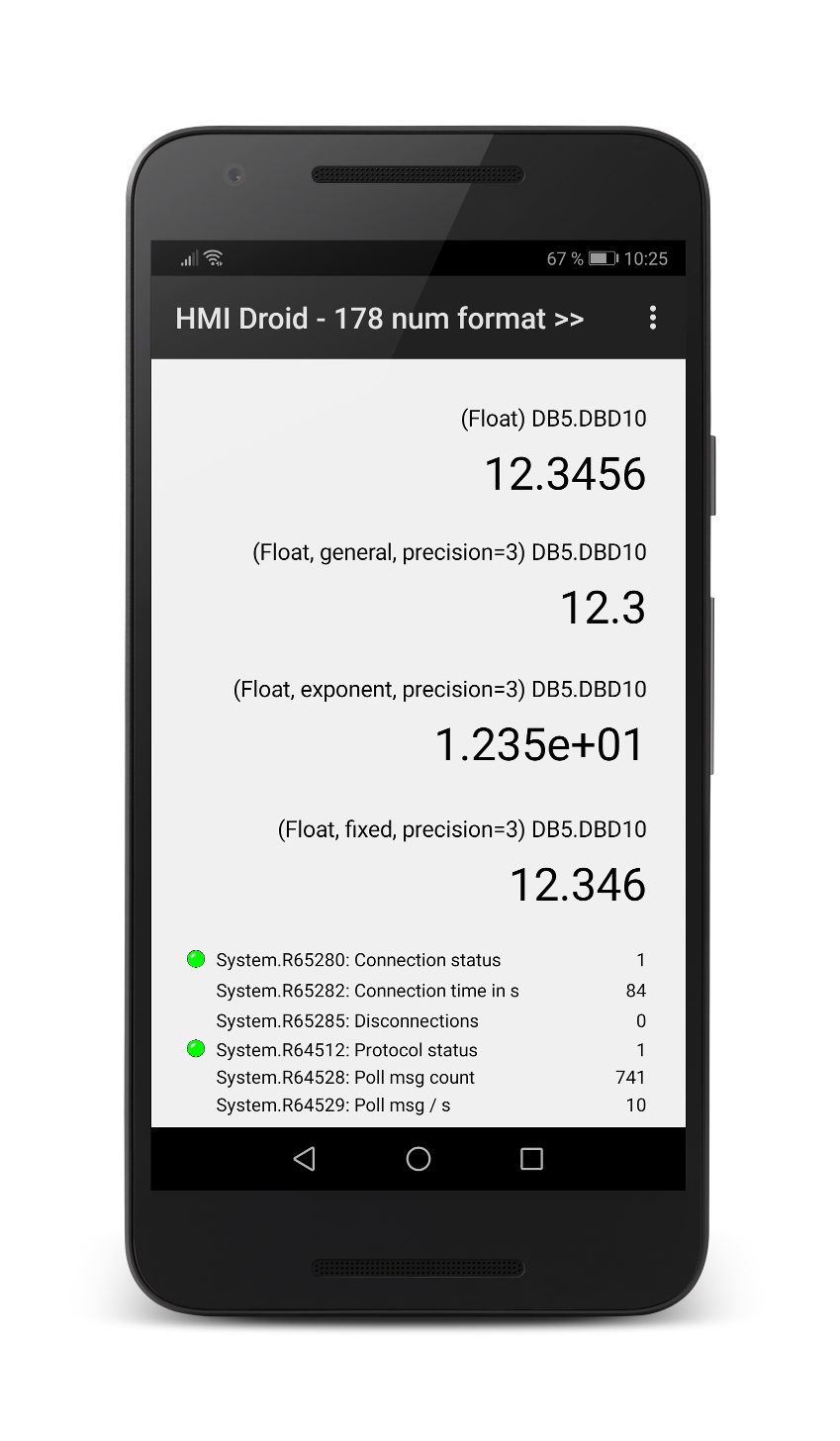
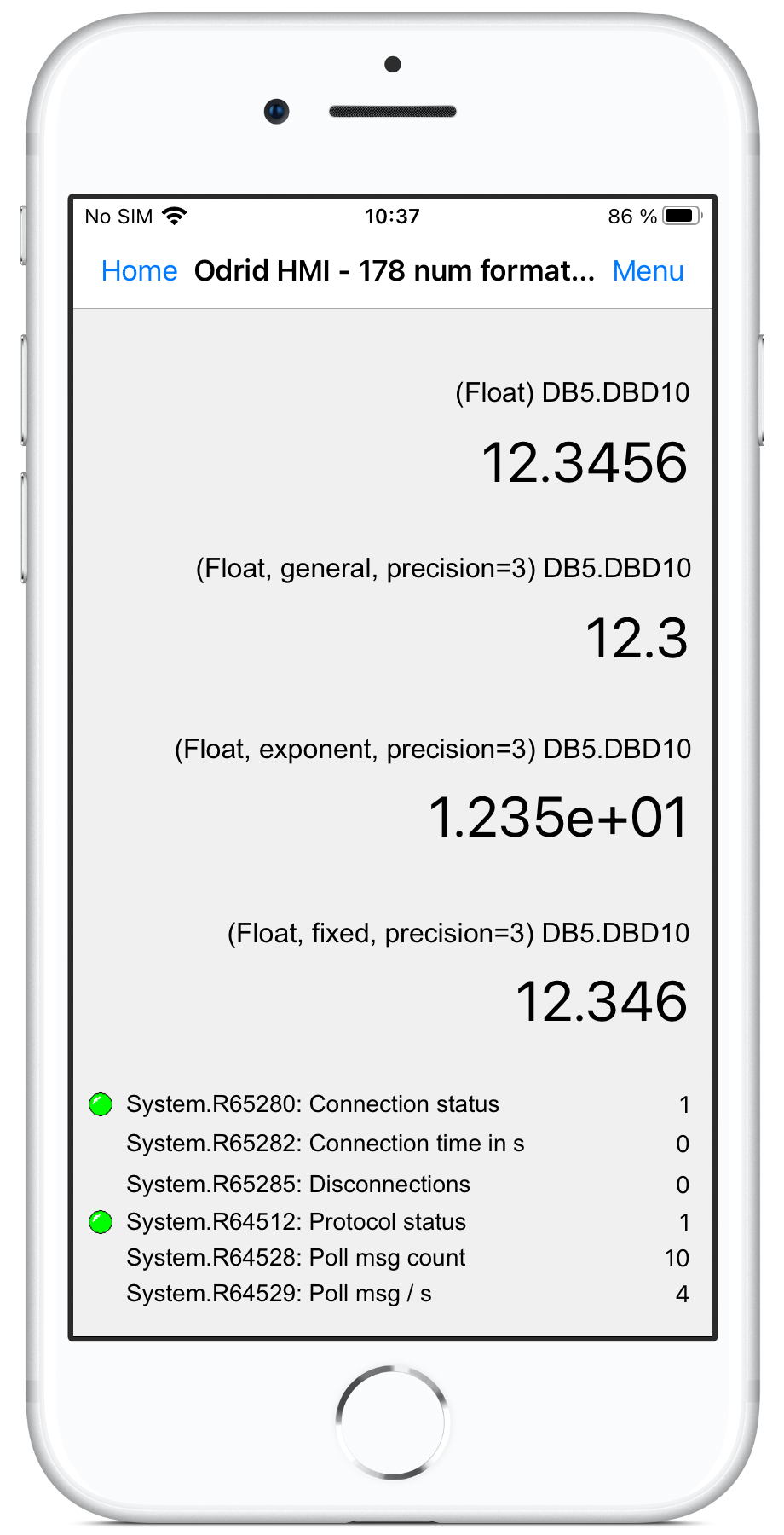
Number formatting
The Number formatting dialog is opened with the "Settings..." button in the dialog for the Numeric variable.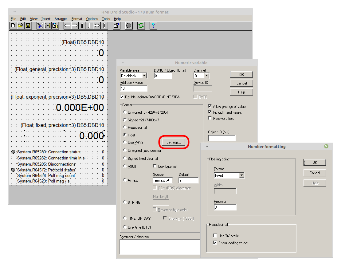
| Property | Description |
|---|---|
| Format | Different floating points formats e.g. General, Exponent and Fixed. |
| Width | Currently not used |
| Precision | Number of decimals when using the Exponent or Fixed format for a floating point number
or number of decimals when using the unsigned fixed decimal and signed fixed decimal formats. Number of digits when using the General format for a floating point number. |
|
|
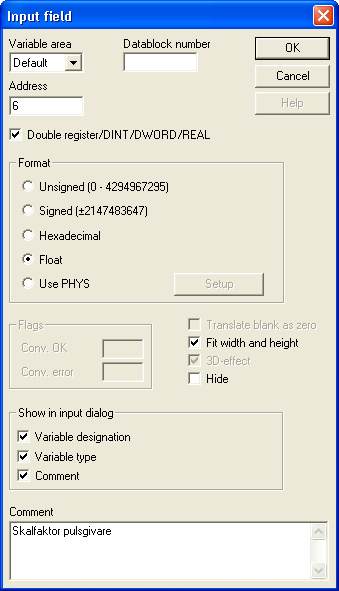
Input field
The object input field is similar to the object numeric variable.
|

|
| Property | Description |
|---|---|
| Channel | The Channel to read variables from. Feature available in HMI Droid Studio 6.7.8 and later. |
| Variable area | Variable area in the controller that the input value should end up in.
|
| Address | Address of the variable. |
| Data block | Number of the data block to be used if the variable area is data block. |
| Double register | Specifies that the variable is a 32-bit variable instead of 16-bit. |
| Format | In what format the numeric variable will be displayed and how the entered value should be interpreted.
|
| Hide | Not implemented presently. |
| Show in the input dialog | Specify what should be displayed in the dialog that is used to enter a value.
|
| Comment | Write an optional comment for the entry field. Text entered here can be shown ( along with the variable name and format ) in the dialog used to enter a value. |
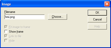
Image
The object image is used to display one or more images which are smaller than the entire workspace. If you want a picture fills entire workspace, you should use the background image instead. In both cases, the image shall be in png format and file name must be specified without path and be exactly the same as for file with respect to uppercase/lowercase characters. Windows makes no difference in the file namesIMAGE.PNG and image.png but in Android and iOS it is the names of
two different files.Store the image files that will be used in the same directory on the PC as the panel files. Always save the panel on the PC in this directory before selecting an image filename. This will make HMI Droid Studio to automatically remove the path from the image filename.
Image files must be transferred to the target device manually, they are not included in the *.led-file for the panels (pages).
Note: The current version of HMI Droid Studio does not support alpha channel (transparency) in images. For best result, use images with the same background color as the panel (page).
Update: HMI Droid Studio 6.7.8.3121 (beta) and later supports alpha channel (transparency) in images.
Warning: The target device may run out of memory if very large images are used!
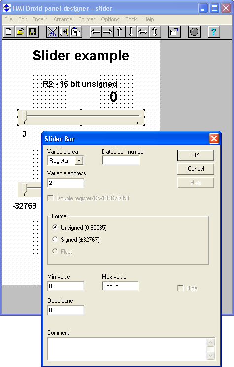
Slider Bar
A Slider Bar is used to change a numeric variable. The change is made in the controller when you let go. A Slider Bar displays the value of the variable in the controller dynamically except just when you pull it.
|
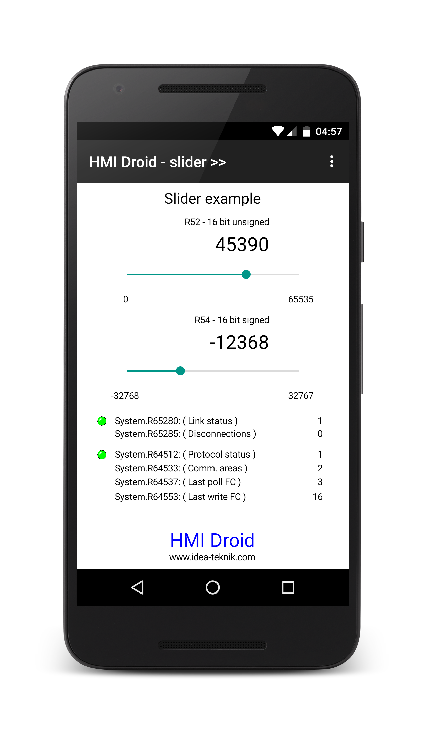
|
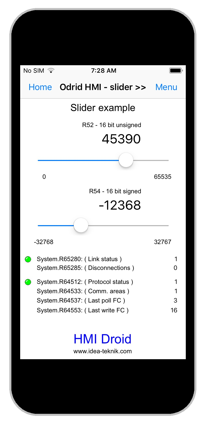
|
In the dialog for configuring a Slider Bar, select the variable area and enter the variable address and desired range.
Minimum and maximum values specified between 0 and 65535 for unsigned and between -32768 and 32767 when signed.
Max must be greater than min.
Dead zone helps finding a zero value that is not in an end position.
The Update immediately option available in HMI Droid Studio V6.7.6.1061 and later, will write a new value to the PLC as soon as the Slider is moved. This feature requires a fairly fast connection to the PLC.
Currently only 16 bit integer values are supported but 32 bit integer and floats will be implemented in the next major update.
Update: In HMI Droid 1.7.8.99, the type for the variable can be set to BYTE by entering the following directive in the comment:
$typeOverride="byte";
The BYTE datatype can be used with the Siemens S7 Communication protocol driver.
The example panel (page) in the screenshot above is available for download.
slider.led
Download the file and open it in HMI Droid Studio.
Modify the IP-address in the communication parameters settings to match your PLC/controller.
Use the Test run feature or transfer the file to the Android or iOS-device.
This panel (page) is 320 dp wide. On some devices the panel scaling feature therefore must be enabled to fit the workspace.
Upcoming scripts in HMI Droid Studio 6.7.8.3126
The Slider object will support the following script properties.
| Property name | Access | Description |
|---|---|---|
| intValue | Read/Write | The current value as a 32-bit unsigned integer. Write is possible in the Local variable area only. |
Bar Indicator
The Bar Indicator Object is used to display the value of a numeric variable using a horizontal or vertical bar.

|

|

|
In the dialog for configuring a bar indicator you specify eg variable area and variable address as well as desired range.
Minimum and maximum values specified between 0 and 65535 for unsigned and between -32768 and 32767 when signed.
Max must be greater than min.
The positive direction for the bar indicator is always to the right or up.
Status bits for Underflow and Overflow can be read at address 16:0 and 16:1 via the variable area Objects.
Note: Currently only 16 bit integer values are supported but 32 bit integer and floats will be implemented later.
Update: In HMI Droid 1.7.8.99, the type for the variable can be set to BYTE by entering the following directive in the comment:
$typeOverride="byte";
The BYTE datatype can be used with the Siemens S7 Communication protocol driver.
The value can be multiplied with -1 by entering the directive
$changeSign="true"; in the comment section. When using this feature, the signed format must be used.In HMI Droid 1.7.8.121 (Beta) and later, a diagnostic dialog can be opened by making a long press on the Bar Indicator object.
Upcoming scripts in HMI Droid Studio 6.7.8.3126
The Bar indicator object will support the following script properties.
| Property name | Access | Description |
|---|---|---|
| intValue | Read/Write | The current value as a 32-bit unsigned integer. Write is possible in the Local variable area only. |
| overflow | Read only | True (1) if the currrent value is larger than max. |
| underflow | Read only | True (1) if the currrent value is less than min. |
Chart / Line Graph
Line Graphs can be used to show a number of numeric values as a curve. The function can used e.g. to display trend graphs.Note: The PLC/controller must do the logging and provide a table containing all values with the first value at the specified address.

|

|

|
In the dialog for configuring a line chart you can specify, among other things variable area and variable address as well as desired range.
Max number of values must be greater than 1 and less or equal to 1024.
Minimum and maximum values specified between 0 and 65535 for unsigned and between -32768 and 32767 when signed.
Max must be greater than min.
Currently only 16 bit integer values are supported but 32 bit integer and floats will be implemented later.
The line graph can calculate the minimum, maximum, mean, standard deviation, coefficient of variation and difference between maximum and minimum. These values can be read from the local variable area. The address in the local variable area is calculated by adding the local base address and the index for the statistical function.
| Index | Function | Format |
|---|---|---|
| 0 | Number of values within the range. | Unsigned |
| 20 | The minimum value of all values within the range. | Same as data |
| 22 | The maximum value of all values within the range. | Same as data |
| 24 | The span, ie the highest value minus the lowest value. | Same as data (Unsigned from V1.6) |
| 26 | The average of all values within the interval. | Same as data |
| 30 | Standard deviation. | Unsigned |
| 34 | Coefficient of variation in % x 0.01 ie 1000 corresponds to 10.00%. | Same as data (Unsigned from V1.6) |
| 50 | Difference between first and last value. (Upcoming feature.) | Unsigned |
| 52 | Difference between last and first value. (Upcoming feature.) | Unsigned |
| 999 | Last reserved variable address. |
Logging mode (experimental)
Directives to be entered in the comment section:
| $logging="1"; | Enables the loggning mode. | |
| $interval="NNN"; | Sampling interval times 100 ms. |
Register addresses in the Objects area.
| 1024 | Sampling interval times 100 ms. Read/write. | |
| 1026 | 1 = run, 0 = stop. Read/write. | |
| 1027 | 1 = clear log. Write only. |
The bit address for the start/stop bit can be entered as 1026:0 using the Modbus address format.
Upcoming scripts in HMI Droid Studio 6.7.8.3126
The Line graph object will support the following script properties.
| Property name | Access | Description |
|---|---|---|
| start | Write only | Start the logging. |
| stop | Write only | Stop the logging. |
| reset | Write only | Clear the log. |
| statIntCount | Read only | Number of values within the range. |
| statIntAverage | Read only | The average of all values within the interval. |
| statIntMax | Read only | The maximum value of all values within the range. |
| statIntMin | Read only | The minimum value of all values within the range. |
| statIntSpan | Read only | The span, i.e. the highest value minus the lowest value. |
| statIntStdDev | Read only | Standard deviation. |
Checkbox
With the checkbox it's easy to display and manipulate boolean variables.

|

|

|
Note: Checkboxes in the Android version of HMI Droid will not be located exactly the same as in HMI Droid Studio.
iOS does not include native radio buttons and checkboxes.
Upcoming scripts in HMI Droid Studio 6.7.8.3126
The Checkbox object will support the following script properties.
| Property name | Access | Description |
|---|---|---|
| intValue | Read only | True (1) if the checkbox is checked. False (0) otherwise |
Radio button
With the radio button it is easy to view and manipulate numeric variables of integer type.The radio buttons that uses the same variable will form a group.
Buttons in a group must use unique values e.g. 1, 2, 3 etc.

|

|

|
Note: Radio buttons in the Android version of HMI Droid will not be located exactly the same as in HMI Droid Studio.
iOS does not include native radio buttons and checkboxes.
Update: In HMI Droid 1.7.8.99, the type for the variable can be set to BYTE by entering the following directive in the comment:
$typeOverride="byte";
The BYTE datatype can be used with the Siemens S7 Communication protocol driver.
Upcoming scripts in HMI Droid Studio 6.7.8.3126
The Radio button object will support the following script properties.
| Property name | Access | Description |
|---|---|---|
| intValue | Read only | True (1) if the radio button is checked. False (0) otherwise. |
ST Program Block
A ST (Structured Text) Program Block contains program code that will execute in the panel context.The ST program block in HMI Droid V2.0 implements a subset of the IEC 61131-3 Structured Text programming language and can access variables in the controller/plc as well as the local and system variables areas in HMI Droid.
All variables referenced by the ST program code will be automatically polled from the PLC/controller in the same way as any variables used by other objects such as LEDs, numeric variables and bar indicators.
The ST Program Blocks are hidden in the HMI Droid but visible in the HMI Droid Studio.
The lightning fast compiler will be integrated in the HMI Droid Studio and the compiled HMI Droid Structured Text program is stored in the *.led files. The HMI Droid Structured Text source code is stored in files with extension
.hmidst and can be edited using any text editor including Notepad.It will also be possible to test run the ST Program Blocks in HMI Droid Studio using the test run panel (page) feature.
Arithmetic operators:
| Operator name | Syntax |
|---|---|
| Addition | a + b |
| Subtraction | a - b |
| Unary plus | +a |
| Unary minus | -a |
| Multiplication | a * b |
| Division | a / b |
| Modulo | a mod b |
Relational operators:
| Operator name | Syntax |
|---|---|
| Equal to | a = b |
| Not equal to | a <> b |
| Greater than | a > b |
| Less than | a < b |
| Greater than or equal to | a >= b |
| Less than or equal to | a <= b |
Bitwise operators:
| Operator name | Syntax |
|---|---|
| Logic not | NOT a |
| Bitwise or | a OR b |
| Bitwise and | a AND b |
| Bitwise xor | a XOR b |
Logic operators:
| Operator name | Syntax |
|---|---|
| Logic not | NOT a |
| Logic and | a AND b ( a & b ) |
| Logic or | a OR b |
| Logic xor | a XOR b |
Data types
The following datatypes will be supported initially.| BOOL | Boolean variable. | |
| INT | 16 bit signed variable. | |
| DINT | 32 bit signed variable. | |
| WORD | 16 bit unsigned variable. | |
| DWORD | 32 bit unsigned variable. | |
| REAL | 32 bit floating point variable. |
Functions
The following functions will be included initially.| Function | Return value | |
|---|---|---|
| abs(x) | Absolute value of x. | |
| acos(x) | Arc cosine value of x. | |
| asin(x) | Arc sine value of x. | |
| atan(x) | Arc tangent value of x. | |
| cos(x) | Cosine value of x. | |
| exp(x) | The exponent of X, i.e. the number e to the power x. | |
| log(x) | Logarithm base 10 of x. | |
| ln(x) | Natural logaritm of x. | |
| round(x) | The closest integer, which may be bigger or smaller than x. | |
| sign(x) | Sign of x as -1, 0 or 1. | |
| sin(x) | Sine value of x. | |
| sqrt(x) | Square root of x. | |
| tan(x) | Tangent for x. | |
| toReal(x) | X with type converted to REAL. | |
| trunc(x) | Integer part for x. |
Some preliminary code examples:
Variable declarations
//

//  Variables in the plcs/controllers

//


VAR_GLOBAL

    errorCode AT plc0.register.r200 : WORD;

    errorFlag AT plc0.register.r202:1 : BOOL;

END_VAR


//

//  Variables in the local variable area

//


VAR_LOCAL

    start AT local.R400:4: BOOL;

END_VAR


//

//  Private variables

//


VAR_PRIVATE

    temp: INT;

END_VAR


//

//  Typed constants

//


CONST

    pi: REAL = 3.14159;

    the_answer: INT = 42;

END_CONST
Unconditional statements
PROGRAM Example_1


//

//  Example

//


local.R100 := plc0.register.R200 + plc0.register.R201;

local.R101 := plc0.analogin.R150;


END_PROGRAM
Conditional statements
PROGRAM Example_2


//

//  Example showing if-then-else-end_if

//


IF plc0.input.ix0 THEN

    local.R100 := plc0.register.R200 + plc0.register.R201

ELSE

    local.R100 := 0;

    local.R102 := 0;

END_IF


//

// Example showing if-then-endif

//


IF system.firstScan AND (local.R100 < 0 ) THEN

    local.R100 := 0;

END_IF


//

//  Example of velocity calculation during linear deceleration

//


dwRemaining_distance := plc0.register.dwTargetPos - plc0.register.dwCurrentPos;

fDirection := sign( dwRemaining_distance );

plc0.register.fVelocity := fDirection * fSpeedFactor * sqrt( abs( dwRemaining_distance ) );


END_PROGRAM
Function block
The following types of function blocks will be available.- Bitwise operations e.g. AND, OR, XOR, NOT, BITCOUNT
- Conversion functions e.g. INT_TO_REAL, WORD_TO_REAL, ROUND, TRUNC
- Comparsion operations e.g. EQ, NE, GT, GE, LT, LE
- Mathematical functions e.g. ABS, SQR, SQRT, LN, EXP, LOG, 10^X, INV
- Mathematical operations e.g. ADD, SUB, MUL, DIV, MOD
- Shift functions e.g. ROL, ROR, ASL, ASR, SHL, SHR
- Special functions e.g. SCALE, HI_BYTE, LO_BYTE, MIN, MAX
- Trigonometrical functions e.g. SIN, COS, TAN, ASIN, ACOS, ATAN
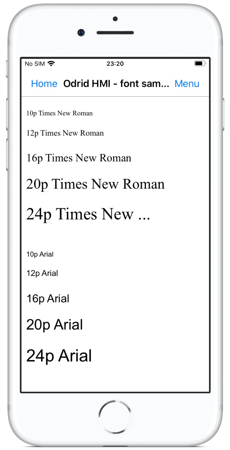
Font
For all Objects that displays text, the typeface name, style, text size and Character set can be selected in the Font dialog.

|

|
|
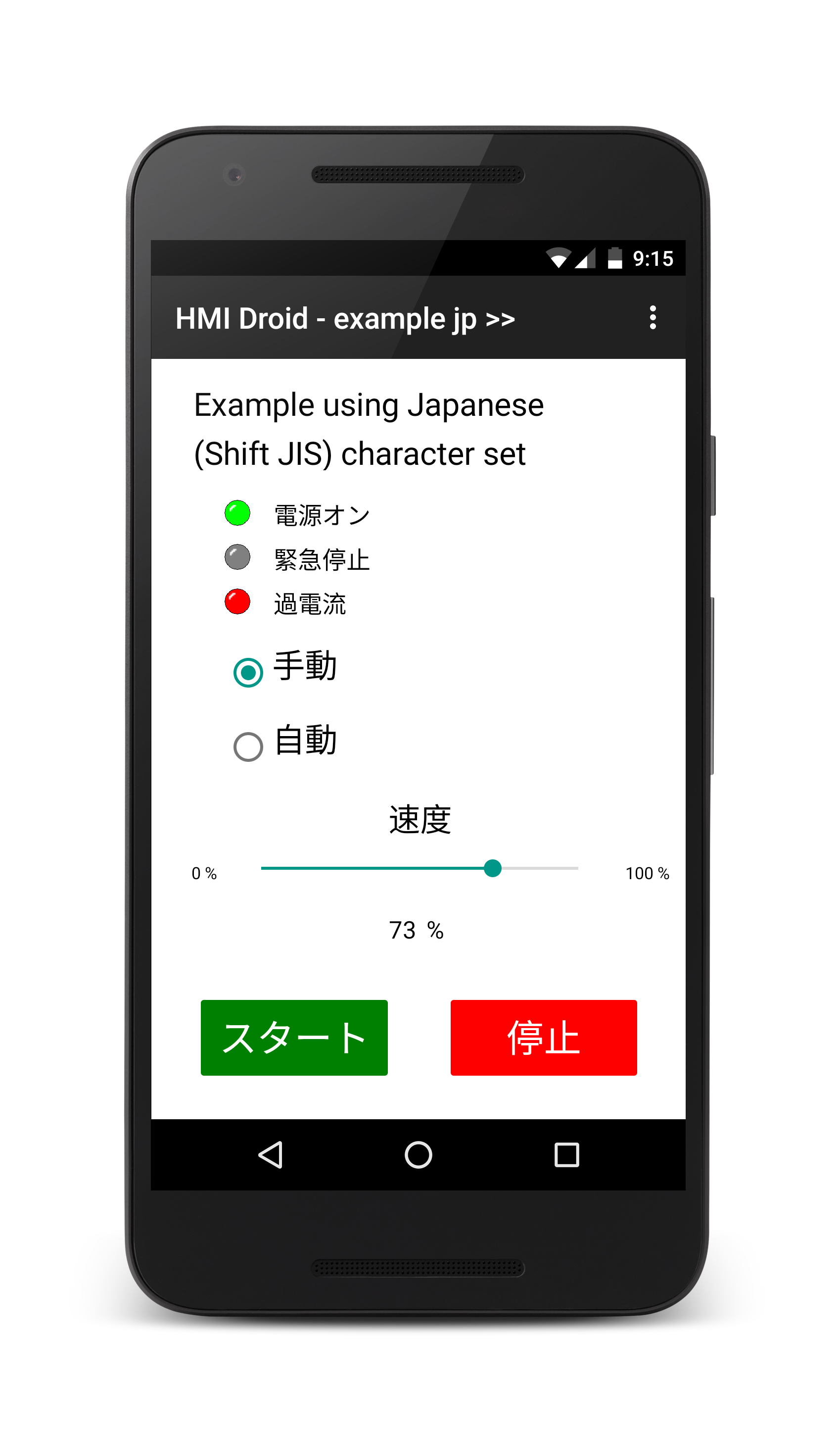
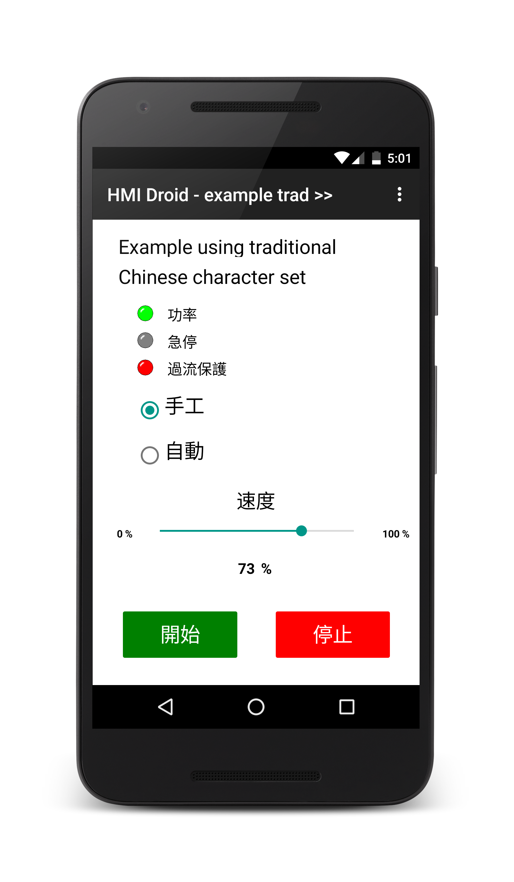
Character set
For all objects that displays text, the character set can be selected in the font dialogue.Currently the following character sets are supported: Arabic, Baltic, Central European, Chinese (GB2312, BIG5), Cyrillic, Eastern European, Greek, Hebrew, Japanese (Shift JIS), Korean, Turkish and Western.
The iOS-version of HMI Droid currently supports the Central European, Cyrillic, Eastern European, Greek, Hebrew, Japanese (Shift JIS), Turkish and Western character sets.
Update: The iOS version 1.0.22 has (experimental) support for Chinese character sets.
Note: HMI Droid Studio will use the Western character set by default.
Below are a few examples of different character sets.
| Western | Cyrillic | Japanese (Shift JIS) | Traditional chinese |

|

|
|
|
The example panel (page) in the screenshots above is available for download.
example en.led
example UA.led
Text color
This command can be used to change the text color for the selected objects. Virtually any color can be used instead of the just about 16 predefined colors available in the font dialog.In HMI Droid Studio 6.7.8.3124 (beta) and later, custom colors are retained between sessions.
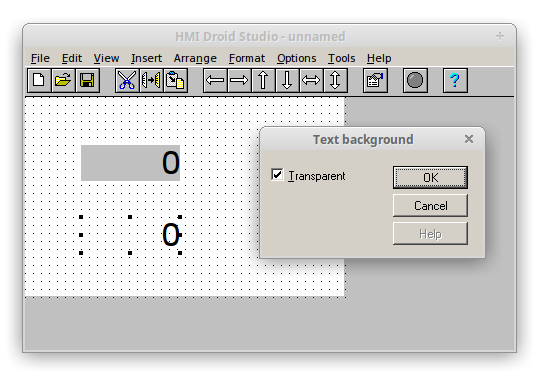
Text background
Controls the opacity of the Text, Date, Time and Numeric variable objects. This property has currenly no effect in the Android and iOS/macOS-versions of HMI Droid.However, this feature will be implemented later. Meanwhile you should keep the Transparent option enabled.
LED type
Choose size for selected LEDs.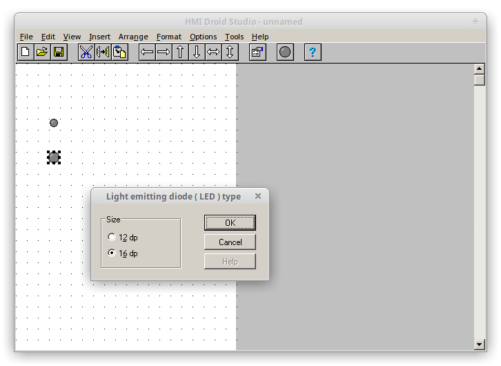
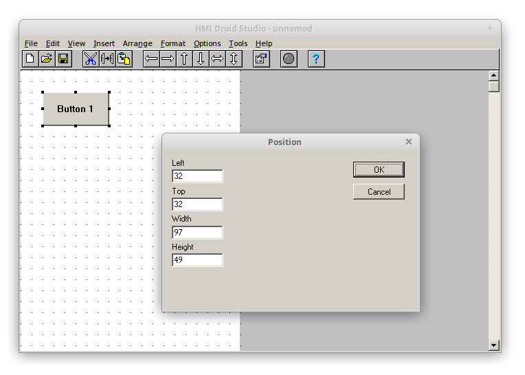
Position
Changes the position and size for selected Objects numerically.Note: Size can not be changed for LEDs with fixed size or for Objects with the Fit width and height option selected.
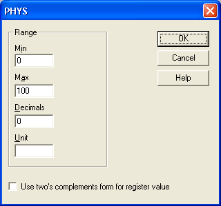
PHYS (Scaling)
The PHYS function can be used to translate a variable value to a certain physical value and back for numeric variables and input fields. Variable value range between 0 and 65535 can be scaled to represent a certain range, for example, an analog input or output.PHYS is configured in its own dialogue where you specify minimum value, maximum value, number of decimal places and optionally a unit.
The value for Max can be set lower than the value for Min for achieving a negative slope. A typical usage is for "reversing" the output from an ultra-sonic transducer that measures the top of the water level from the top of the tank.
If the variable is signed ie covering -32768 to 32767 instead of 0 to 65535, select "Use two's complement form of register value".
By choosing suitable values for min, max and decimals you can also utilize PHYS to handle integer values as tenths or hundredths.
|

|

|
The example panel in the screenshots above is available for download.
fixed.led
| Min | Max | Decimals | Two's compl. | Variable value | Scaled value |
|---|---|---|---|---|---|
| 0 | 6553 | 1 | No | 0 .. 65535 | 0 .. 6553.5 |
| 0 | 655 | 2 | No | 0 .. 65535 | 0 .. 655.35 |
| -3277 | 3277 | 1 | Yes | -32768 .. 32767 | -3276.8 .. 3276.7 |
| -328 | 328 | 2 | Yes | -32768 .. 32767 | -327.68 .. 327.67 |
PHYS Example 1
A temperature sensor with a range of -30 to +70 °C is connected to an analog input on a RievTech/xLogic PLC. The analog input on this PLC uses a range of 0 to 1000 units. The values for Max and Min in the PHYS setup dialog box corresponds to a range of 0 to 65535 so the Max value has to be calculated using the formula below.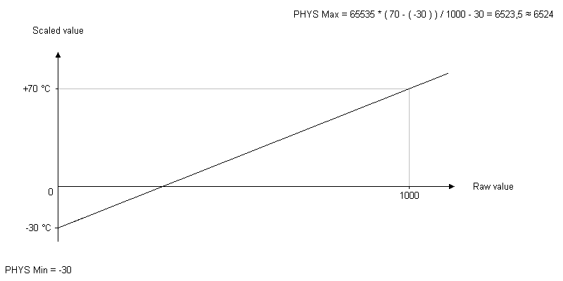
PHYS Example 2
An ultrasonic sensor is used for measuring the water level from the top of a tank. The value from the sensor is in the range 0 to 4095 and a high value corresponds to a low water level. By entering a value for Max that is less than the value for Min, the scaled value will be "reversed". To calculate the Max value, extrapolation to a raw value of 65535 is required.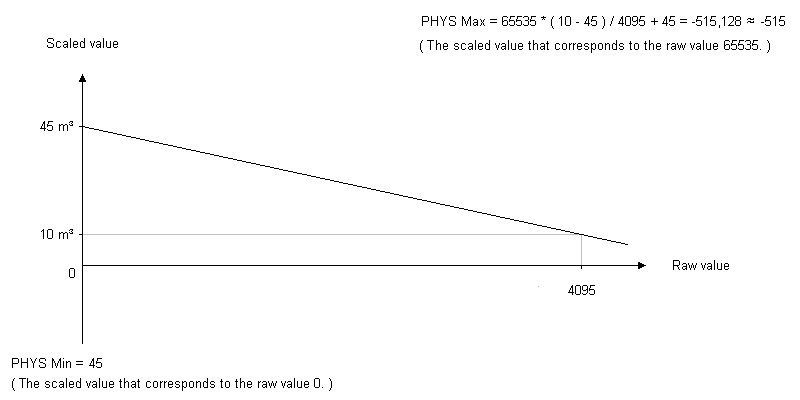
Scripts (Upcoming feature)
HMI Droid Studio 6.7.8.3126 and later supports scripts entered in the comment area for the GUI-objects.Note: Neither HMI Droid (Android) nor Odrid HMI (iOS/macOS) contains any support for scripts yet.
A script must be preceded by a dollar sign ($) except when inside an if or else clause.
Statements
<property> = <expression>;

<object-name>.<property> = <expression>;

return;

if (<expression>) <statement>;

if (<expression>) <statement> else <statement>;

{

  <statement>;

  <statement>[;]

}
Mathematical operators
+, -, *, /, %
Logical operators
&&, ||, !
Bitwise operators
&, |, ^
Comparsion operators
>, <, >=, <=, ==, !=
Shift operators
<<, >>
Using properties in expressions
<property>
|
Read property in this object. | |
<object-name>.<property>
|
Read property in another object. |
Special properties
| Property name | Access | Description |
|---|---|---|
| firstScan | Read only | True (1) during the first cycle, 0 otherwise. |
| pulse1Hz | Read only | True (1) during one cycle every second, 0 otherwise. |
The data type used in the scripts is 32-bit unsigned integer.
Address format
The command address format in the format menu is used to select how the bit addresses for boolean variables should appear in the dialogues that are used to configure LEDs, Buttons and Checkboxes.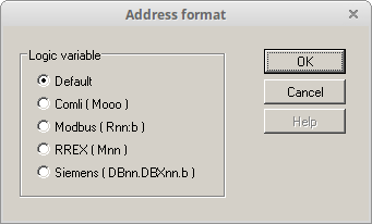
| Option | Variable area | How the bit address is displayed |
|---|---|---|
| Default | Decimal between 0 and 65534. | |
| COMLI | Octal between 0 and 37777. | |
| Modbus | Default or Register | As a register address:bit number with bit number between 0 and 15. Register address specified in decimal with no leading 'R'. The highest bit address that can be used is currently R4095:14 but it will be extended to R65535:15 in the future. |
| Modbus | I or Q | Decimal between 0 and |
| Siemens | As byte.bit with bit number between 0 and 7. |
Variable area I and Q are available if you have chosen Modbus/TCP class 1 or Modbus RTU class 1.
Note: For variable area Objects, the Modbus address format should be used.
Table showing principle for bit addresses
| Default (decimal) | COMLI (octal) | Modbus (Rnn:n) | Siemens (DBnn.DBXnn.b) |
|---|---|---|---|
| 0 | 0 | 0:0 | 0.0 |
| 1 | 1 | 0:1 | 0.1 |
| 2 | 2 | 0:2 | 0.2 |
| 3 | 3 | 0:3 | 0.3 |
| 4 | 4 | 0:4 | 0.4 |
| 5 | 5 | 0:5 | 0.5 |
| 6 | 6 | 0:6 | 0.6 |
| 7 | 7 | 0:7 | 0.7 |
| 8 | 10 | 0:8 | 1.0 |
| 9 | 11 | 0:9 | 1.1 |
| 10 | 12 | 0:10 | 1.2 |
| 11 | 13 | 0:11 | 1.3 |
| 12 | 14 | 0:12 | 1.4 |
| 13 | 15 | 0:13 | 1.5 |
| 14 | 16 | 0:14 | 1.6 |
| 15 | 17 | 0:15 | 1.7 |
| 16 | 20 | 1:0 | 2.0 |
| 17 | 21 | 1:1 | 2.1 |
| 18 | 22 | 1:2 | 2.2 |
| 19 | 23 | 1:3 | 2.3 |
Communication parameters
To enable the use of HMI Droid/Odrid HMI with different controllers, you can specify the communication parameters for the connection and the controller per panel (page). The communication parameters you specify per panel (page) will always override the default settings made in the HMI Droid app on the target device.When navigating to a panel (page), a new connection will be established if e.g. connection type, IP address, or port number differs from the current connection.
Note: For Bluetooth (SPP) the MAC-address must be in upper case. Example: 12:34:56:AB:CD:EF
Note: It's recommended to tick the left check box for all unused parameters like e.g. Life bit, 32-bit registers and Word swap. This will prevent activating the options by mistake from the settings in the Android or iOS-device.
")
Typical setup for communication with Siemens LOGO! 0BA8.
Device settings
Some of the newer communication parameters are not stored in the *.led-files. Instead they have to be set using the Device settings command before using the Test run feature.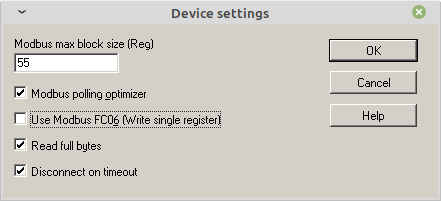
| Feature | Usage | |
|---|---|---|
| Use Modbus FC06 | Check to use FC06 (write single register) instead of FC16 (write multiple registers) when writing 16-bit integer variables with the Modbus/TCP protocol. | |
| Read full bytes | Uncheck when using e.g. Eaton easyE4 or e.g. IO-devices with less than 8 inputs or outputs. | |
| Disconnect on timeout | Uncheck when using the Modbus RTU protocol with multiple Device ID on the same channel. |
Note: Read full bytes and Disconnect on timeout are available in HMI Droid Studio 6.7.8.3119 (upcoming beta) and later.
Connection types
The different connection types available in our HMI apps and in the free-of-charge development tool on different platforms.| Connection type | HMI Droid (Android) | Odrid HMI (iOS/macOS) | HMI Droid Studio (Win32) | |||
|---|---|---|---|---|---|---|
| Bluetooth Classic | Yes | No | Yes | |||
| Bluetooth LE | No | Yes | No | |||
| TCP/IP | Yes | Yes | Yes | |||
| UDP/IP | Yes | No | No |
Bluetooth Classic
Uses MAC-address to connect to a Bluetooth device, the Android version can scan for Bluetooth devices if no MAC-address is entered.Note: The SPP (Serial Port Profile) checkbox must be ticked to use Bluetooth Classic on Android devices.
Bluetooth LE
This connection type uses the Microchip Transparent UART service to connect to a Bluetooth LE device.Enter the name of the device in the communication settings.
Transparent UART Service UUID:
49535343-FE7D-4AE5-8FA9-9FAFD205E455
|
Service Characteristics UUIDs:
| Write to BLE device | 49535343-8841-43F4-A8D4-ECBE34729BB3 |
|
| Read from BLE device | 49535343-1E4D-4BD9-BA61-23C647249616 |
TCP/IP
Uses ip-address (or host name) and port number.UDP/IP
Uses ip-address (or host name) and port number.Communication protocols
Currently, the following communication protocols are available in the Android version of the HMI Droid.- COMLI
- Modbus/TCP [class 0]
- Modbus/TCP class 1
- Modbus RTU class 1
- SattBus COMLI
- Siemens Fetch/Write
- Siemens S7 Communication (ISO-on-TCP)
COMLI
This protocol can be run over either TCP/IP on Wi-Fi or via Bluetooth.The messages that are implemented is 0, 1, 2, 3 and 4, which means that you can access the registers 0 to 3071 (decimal) and flags between 0 and 37777 (octal).
With COMLI you can write individual bits without affecting other flags in the same byte or word.
A controller that uses COMLI normally have "big-endian" byte order, which means that in "double register" the high word is stored first.
Note: The COMLI protocol is not available in the iOS and Windows versions of HMI Droid.
Modbus/TCP [Class 0]
This protocol can be run over TCP/IP or UDP and typically uses port 502 in the PLC/controller.The driver for Modbus/TCP [Class 0] uses functions 3 and 16 of the Modbus specification. Maximum 64,512 Holding registers can be addressed. The first register always has address 0 even if the designation for the first register in the controller/PLC is 40001 or 400001.
Boolean variables ( = memories/flags ) can be mapped to bits in the Holding registers by entering the address as nn:b, where nn is the register number and b is the bit number between 0 and 15. Bit 0 is the least significant bit in the register and have weight 20 which is the first. Bit 15 is the most significant bit in the register and have weight 215 which is 32768.
With this protocol, you write always at least two bytes at a time. This means that controller should not affect bits in words containing bits HMI Droid will write. One should also not affect bits in the same word as HMI Droid writes from any other system around the same time.
A controller using Modbus normally has "big-endian" byte order, which means that in "double register" the high word is stored first.
Starting with version 1.6, it is possible to choose whether high or low word is stored in the first register using the Word Swap option.
Typical communication settings for Modbus/TCP
| Parameter | Value | Comment |
|---|---|---|
| Connection type | WiFi (TCP/IP) | Ethernet UDP (UDP/IP) is possible. |
| IP-address | xxx.xxx.xxx.xxx | Normally the IP-address for the controller. |
| Port | 502 | Range = [1, 65535] |
| MAC-address | N/A | Used for Bluetooth connections. |
| Use SPP | N/A | Used for Bluetooth connections. |
| Protocol | Modbus/TCP [Class 0] or Modbus/TCP Class 1 | |
| Device ID | 1 | Range = [1, 255] |
| Default DB | N/A | |
| Enable life bit | Optional | |
| Address for life bit | Optional | |
| 32-bit register | For xLogic Easy / RievTech PLC | |
| Word Swap | Optional | Modbus uses big-endian byte order. |
| Poll interval in ms | Optional | Recommended value e.g. 25 or 100. |
Modbus/TCP class 1
The same basic function as Modbus/TCP [class 0] but boolean variables for e.g. LEDs and Buttons can be connected to Discrete Inputs and Coils instead of just bits in the Holding registers by selecting variable area I for Discrete Inputs and variable area Q for Coils.The following functions in the Modbus specification are used for inputs and outputs in variable areas I, AI and Q.
Reading digital inputs: Function 2 (Read Input Status)
Reading analog inputs: Function 4 (Read Input Registers)
Reading Outputs: Function 1 (Read Coil Status)
Writing Outputs: Function 5 (Force Single Coil)
Note: By default HMI Droid/Odrid HMI reads full bytes when reading Discrete Inputs and Coils and the bytes will be aligned modulo 8.
HMI Droid Studio 6.7.8.3101 and HMI Droid 1.7.8.101 can be configured to use Modbus FC06 (Write single register) instead of FC16 (Write multiple registers) when writing a 16 bit value to a Holding register.
In HMI Droid Studio 6.7.8.3101, FC06 is enabled in the Device settings.
In HMI Droid 1.7.8.101, FC06 is enabled in the settings for controller.
Modbus RTU class 1
Like Modbus/TCP class 1 but shorter header and CRC16 checksum. In most cases a serial port is used on the controller. Can be used with connection types WiFi (TCP/IP), Efternet UDP (UDP/IP) or Bluetooth.Note: There is currently no support for using FC06 with Modbus RTU.
SattBus COMLI
"Encapsulated" COMLI SattBus over Ethernet according to "SattBus Message Specification 2.0."Connection type must be set to "Ethernet UPD" (UDP/IP) and port number is usually set to 2999.
The SattBus COMLI protocol is not available in the iOS-version of HMI Droid.
Siemens Fetch/Write
This protocol can be run over TCP/IP and uses two ports on the controller. One port for "Fetch passive" and one port for the "Write passive". For Siemens CP 343-1 is normally port number between 1025 and 65535 used. The port number you enter in the settings will be used for Fetch and the port number +1 will be used for write.Step 7 uses byte addressing of the variables. 16-bit memory words that are in sequence are named eg MW0, MW2, MW4 or DBnn.DBW0, DBnn.DBW2, DBnn.DBW4 etc.
The driver for the Siemens Fetch/Write protocol can address bytes 0-127 for inputs, outputs and memory. If you use the the data block you can address words 0-2047 in the data block which corresponds to byte 0 and 1 to byte 4094 and 4095. Data block between 1 and 255 can be used.
With this protocol, you write always full byte at a time, and in the data block always two bytes. This means that the controller must not write bits in bytes, or words of the data block that contains bits that HMI Droid will be writing.
A controller that uses Siemens Fetch/Write normally have "big-endian" byte order, which means that in a double word the low word is stored first.
The Siemens Fetch/Write protocol is not available in the iOS-version of HMI Droid.
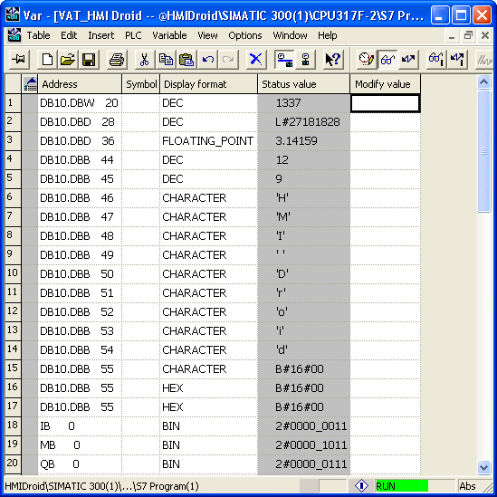
|

|
Siemens S7 Communication (ISO-on-TCP)
Basically the same functions as the Siemens Fetch/Write-protocol.Connection type should be set to WiFi (TCP/IP) and Port number should normally be set to 102.
HMI Droid will connect as an OP. Make sure that the hardware configuration for the Siemens S7 PLC has enough connection resources for OP.
In version V1.7.2 of HMI Droid, other values for rack and slot can be used for connecting HMI Droid to Siemens S7-1200, S7-1500 and LOGO!.
Currently, only the first 255 data blocks can be used but the range will be expanded.
Update: In HMI Droid 1.7.7.85 (Android) the maximum adressing range is 65535 datablocks.
The address range for Datablocks, Inputs, Outputs and Memory is 2048 words (4096 bytes).
This protocol has been tested with the following controllers:
- CPU 314 + CP 343-1
- CPU 315 PN/DP
- CPU 317F-2 DP + CP 343-1
- CPU 1212C
- CPU 1214C
- CPU 1215C
- CPU 1510
- LOGO! 0BA8 Watch short demo on YouTube for Android and iOS.
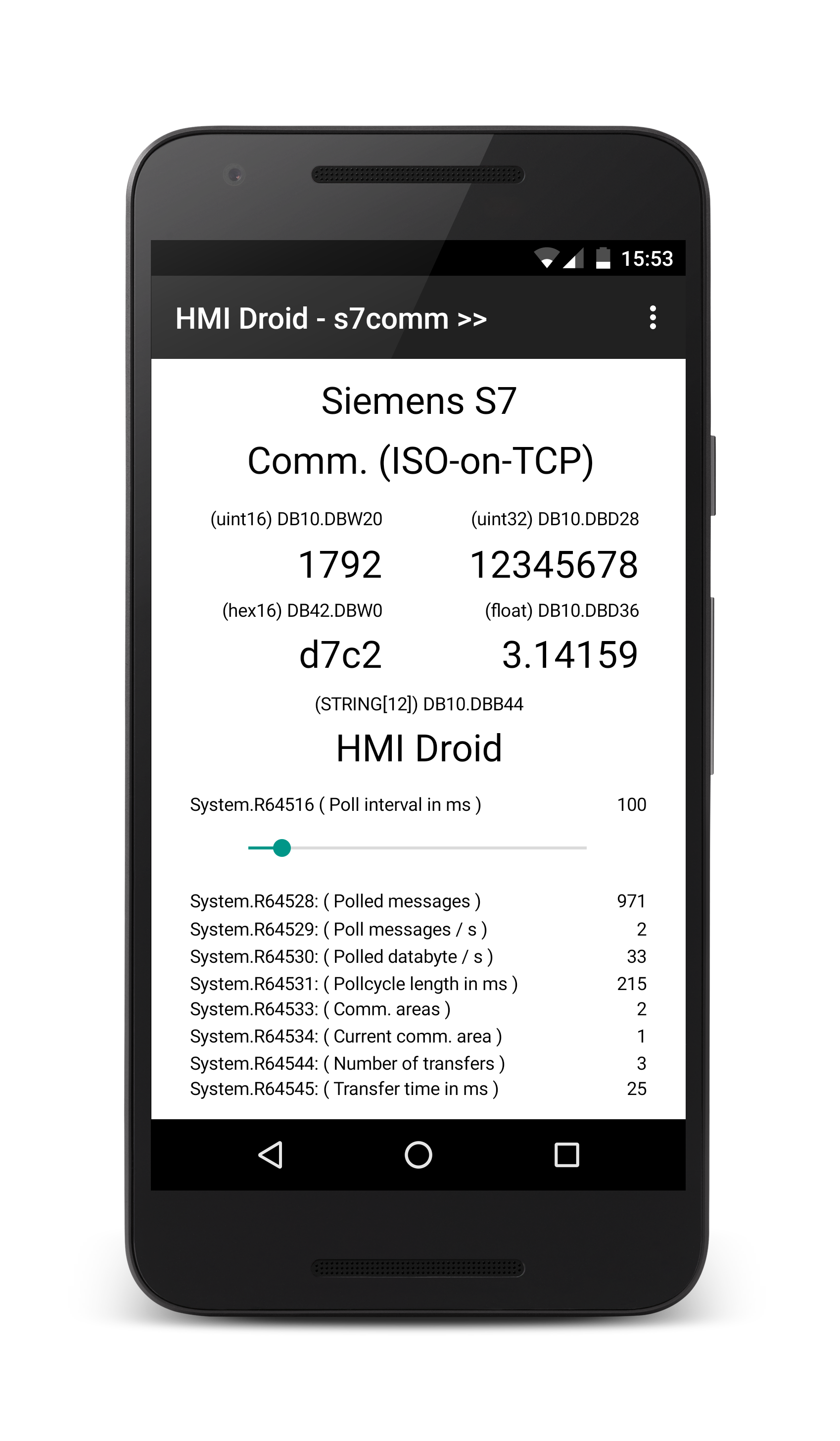
|
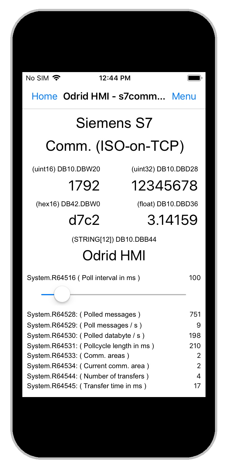
|
Protocols and connections
| Protocol | Bluetooth Classic | Bluetooth LE | TCP/IP | UDP/IP |
|---|---|---|---|---|
| COMLI | BT-adapter | BT-adapter | Port server | Port server |
| Modbus/TCP | No | No | Yes | Possible |
| Modbus RTU | BT-adapter | BT-adapter | Port server | Possible |
| SattBus COMLI | No | No | No | Yes |
| Siemens Fetch/Write | No | No | Yes | No |
|
Siemens S7 Communication (ISO on TCP) |
No | No | Yes | No |
Variable areas
HMI Droid handles boolean and numeric variables. Different controllers normally store the variables in some specific areas. These areas are referred to and handled differently depending on the selected communication protocol. Therefore, there is a "mapping" of how the variables used in the various items included in a panel (page) are referenced in the controller.Explicit mapping is done by selecting the variable area and possibly also specify the of data block.
If you do not explicitly choose a variable area, then an implicit mapping will be done to the default are chosen for the variable type and the current communication protocol.
The table shows the default mapping occurs and the mappings can be done at present.
| Protocol | Variable type | Data block | Inputs (I) | Memories (M) | Outputs (Q) | Registers | Analog inputs (AI) |
|---|---|---|---|---|---|---|---|
| COMLI | Boolean | Default | Yes | ||||
| Numeric | Yes | Default | |||||
| Modbus/TCP [class 0] | Boolean | --- | --- | --- | --- | Default | --- |
| Numeric | --- | --- | --- | --- | Default | --- | |
| Modbus/TCP class 1 | Boolean | --- | Yes | --- | Yes | Default | Yes |
| Numeric | --- | --- | --- | --- | Default | Yes | |
| Modbus RTU class 1 | Boolean | --- | Yes | --- | Yes | Default | Yes |
| Numeric | --- | --- | --- | --- | Default | Yes | |
| Siemens Fetch/Write | Boolean | Default | Yes | Yes | Yes | ||
| Numeric | Default | Yes | Yes | Yes | |||
| Siemens S7 (ISO on TCP) | Boolean | Default | Yes | Yes | Yes | ||
| Numeric | Default | Yes | Yes | Yes |
In addition to the options for variable area as shown in the table above, you can also choose System, Local, Const and Objects.
The choice System is used to access the system variables.
The choice Local means that the local variables in HMI Droid will be used. This may e.g. used for the line graph statistics functions or in testing and demo purposes. When the possibility to write PLC code type program executed in the HMI Droid and/or the panels will be introduced, the local variables also be used for this.
The variable area Const makes it possible to enter a constant value that can be used for some special purposes.
The variable area Objects makes it possible to access data in other objects.
Example of usage:
Connecting a Bar Indicator to a Numeric variable object that uses PHYS scaling with negative slope.
Modbus addresses
There are at least three different ways a Modbus address can be defined, namely zero-based, one-based, and by Modbus984addressing and different vendors use different standards to denote the variables.
Zero based addresses uses 0 for the first variable and you use the same address in HMI Droid Strudio.
One based addresses uses 1 for the first variable and you have to subtract one (1) from the address before you use in HMI Droid Studio.
Modbus
984addresses typically uses e.g. 40001 or 400001 for the first Holding register, 30001 or 300001 for the first Input register and 10001 or 100001 for the first Discrete input. Omit the first digit and then subtract one (1) from the address before you use it in HMI Droid Studio.
Unfortunately you can not determine what standard that is used just by looking on the address for a certain variable. 40001 can be either a one based address, a zero based address or a Modbus
984address.
Modbus data types
In order to access a specific Modbus data type, you have to choose the matching variable area.| Modbus data type | Variable area | Access | Modbus FC | Bit address range | Word address range |
|---|---|---|---|---|---|
| Holding Register | Register / Default | Read/Write | 03/16 (06) | 0:0 - 4095:14 | 0 - 65534 |
| Discrete Input | I | Read only | 02 | 0 - 65534 | N/A |
| Coil | Q | Read/Write | 01/05 | 0 - 65534 | N/A |
| Input Register | AI | Read only | 04 | 0:0 - 4095:14 | 0 - 65534 |
Note: All addresses are 16 bit in the current version of HMI Droid Studio.
Modbus word order
The Modbus specification does not include any 32 bit variables. Many PLCs and other controllers can use two consecutive 16 bit registers as a 32 bit variable but the order of the high and low words can be different on various devices. Since Modbus uses big-endian byte order, the normal word order in HMI Droid stores the 16 most significant bits in the register with the lower address.When using 32-bits integer or IEEE 754 single precision floats, the word order have to be reversed for some PLCs in the Communication parameters or in the settings in the Android or iOS device.
Using an incorrect setting for word order will make 32-bit integer and floating point variables display the wrong value.
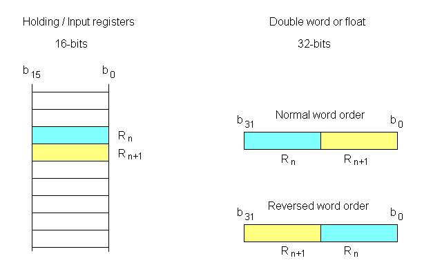
Control word with life bit
The control word works in a similar way as coordination area in Siemens operator panels. The control word's life bit should be monitored by the controller if the panel (page) is used for manual operation of any machine movement. This allows the controller to stop machine movement if the connection between the operator panel and the controller ceases.b0 is the startup bit that goes from 0 to 1 when the panel is connected to the controller.
b1 is the operating mode. (This bit has currently no function.)
b2 is the life bit that toggles with about 0.5 Hz.
Note: The address to the control word is a bit address and is entered in octal format. For Modbus Holding register, multiply the register address by 16 and convert it into octal format.
Example: R400011 has Modbus address 10 and octal bitaddress 240.
Other formats for the control word address, e.g. Rnnn where nnn is the Modbus address to the Holding register, will be implemented in upcoming versions.
Note: In HMI Droid 1.7.8.89 and Odrid HMI 1.3.0, the communication diagnostics dialog displays the address for the control word with life bit in a suitable format for the selected protocol. Modbus will use Rnnn and Siemens S7 Communication (ISO-on-TCP) will use DBxx.DBWyyy.
System registers
There are a number of system registers that can be read for the diagnosis of the connection and the protocol. The system registers can be displayed in a similar way as one showing a variable that refers to the controller. This means that you can customize your own diagnostics and tailor it to your needs. Some systems registers are writable and you can use different GUI objects like Numeric variables, Buttons, Radio buttons or Sliders to manipulate them.System registers for connection
| Address | Function |
|---|---|
| 65280 | Connection status. 0 = disconnected, 1 = connected. |
| 65281 | Last error code. |
| 65282 | Time in seconds the connection has been open. |
| 65285 | Number of disconnections. |
System registers for connection (Bluetooth LE)
| Address | Function |
|---|---|
| 65296 | BLE Status. |
| 65297 | Number of received bytes. |
| 65298 | RSSI in dBm. |
| 65299 | Status for scanning. 0 = not scanning, 1 = scanning. |
| 65304 | Last error. |
| 65312 | Counter for did update state. |
| 65313 | Counter for did discover peripheral. |
| 65314 | Counter for did connect peripheral. |
| 65315 | Counter for did discover service. |
| 65316 | Counter for did discover characteristics for service. |
| 65317 | Counter for did update value for characteristic. |
| 65318 | Counter for did write value for characteristic. |
System registers for protocol.
| Address | Function |
|---|---|
| 64512 | Protocol status. 0 = disconnected, 1 = connected. |
| 64513 | Code for the selected communication protocol (Read-only). |
| 64514 | Enable for the life bit. May be written. |
| 64515 | Reserved for life bit address (Read-only). |
| 64516 | Minimum poll interval in ms. May be written. |
| 64517 | Current Modbus Device ID (Read-only). |
| 64518 | Requested Modbus Device ID (Read/Write). |
| 64519 | Modbus max block size (Read-only). |
| 64520 | Siemens S7 (ISO-on-TCP) error code. |
| 64521 | Siemens S7 (ISO-on-TCP) rack. |
| 64522 | Siemens S7 (ISO-on-TCP) slot. |
| 64523 | Reserved for Modbus protocol driver state (Read-only). 0 = Idle, 1 = Waiting for response. |
System registers for protocol. (Polling/Read)
| Address | Function |
|---|---|
| 64528 | Number of polling queries. May be written. |
| 64529 | Polling queries per second. |
| 64530 | Polled data bytes per second. |
| 64531 | Time for polling cycle in ms. |
| 64532 | Number of retransmissions. May be written. |
| 64533 | Number of communication areas. |
| 64534 | Current communication area. |
| 64535 | Maximum time for polling cycle in ms. May be written. |
| 64536 | Error code during polling. May be written. List with main Modbus exception codes on Wikipedia. |
| 64537 | Modbus: Last sent FC during polling. May be written. Siemens S7: ASCII code for variable area e.g. 'M' for memory. |
| 64538 | Modbus: Start address for the last read request. Read only. Siemens S7: Start byte-address for the last read request. |
| 64539 | Modbus: Number of variables for the last read request. Read only. Siemens S7: Number of bytes for the last read request. |
| 64540 | Modbus RTU response time in ms (Read only). Available in Odrid HMI 1.3.0 and later. |
| 64541 | Modbus optimizer state (Read only). Available in HMI Droid 1.7.8.89 and later and Odrid HMI 1.3.0 and later. |
| 64542 | Modbus: Polled Device ID (Read only). Available in HMI Droid 1.7.8.105 and later. Siemens S7: DBNO for last read request. Available in HMI Droid 1.7.8.111 and later. |
System registers for protocol. (Write)
| Address | Function |
|---|---|
| 64544 | Number of writes. May be written. |
| 64545 | Time for last write in ms. |
| 64546 | Maximum time for write in ms. May be written. |
| 64552 | Error code during write. May be written. List with main Modbus exception codes on Wikipedia. |
| 64553 | Modbus: Last sent FC for write. May be written. Siemens S7: Reserved for last write area ('M', 'I', 'Q', 'D'). |
| 64554 | Modbus: Reserved for last write address. Siemens S7: Reserved for last write address. |
| 64555 | Modbus: Reserved for last write number of variables. Siemens S7: Reserved for last write number of bytes. |
| 64556 | Modbus: Reserved for last write Device ID. Siemens S7: Reserved for last write DBNO. |
System registers for Modbus RTU device enable.
Each Device ID is mapped on a bit in the system registers below for a group of 16 Modbus RTU devices. The LSB (least significant bit) is used for the lowest Device ID in the group.The bit number for a certain Device ID can be calculated as Device ID mod 16.
Note: Bit 0 in the first system register below is not used.
| Address | Function |
|---|---|
| 64560 | Bits for device 0 to 15. |
| 64561 | Bits for device 16 to 31. |
| 64562 | Bits for device 32 to 47. |
| 64563 | Bits for device 48 to 63. |
| 64564 | Bits for device 64 to 79. |
| 64565 | Bits for device 80 to 95. |
| 64566 | Bits for device 96 to 111. |
| 64567 | Bits for device 112 to 127. |
System registers for Modbus RTU device online.
Each Device ID is mapped on a bit in the system registers below for a group of 16 Modbus RTU devices. The LSB (least significant bit) is used for the lowest Device ID in the group.The bit number for a certain Device ID can be calculated as Device ID mod 16.
Note: Bit 0 in the first system register below is not used.
| Address | Function |
|---|---|
| 64576 | Bits for device 0 to 15. |
| 64577 | Bits for device 16 to 31. |
| 64578 | Bits for device 32 to 47. |
| 64579 | Bits for device 48 to 63. |
| 64580 | Bits for device 64 to 79. |
| 64581 | Bits for device 80 to 95. |
| 64582 | Bits for device 96 to 111. |
| 64583 | Bits for device 112 to 127. |
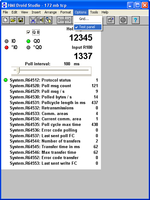
|
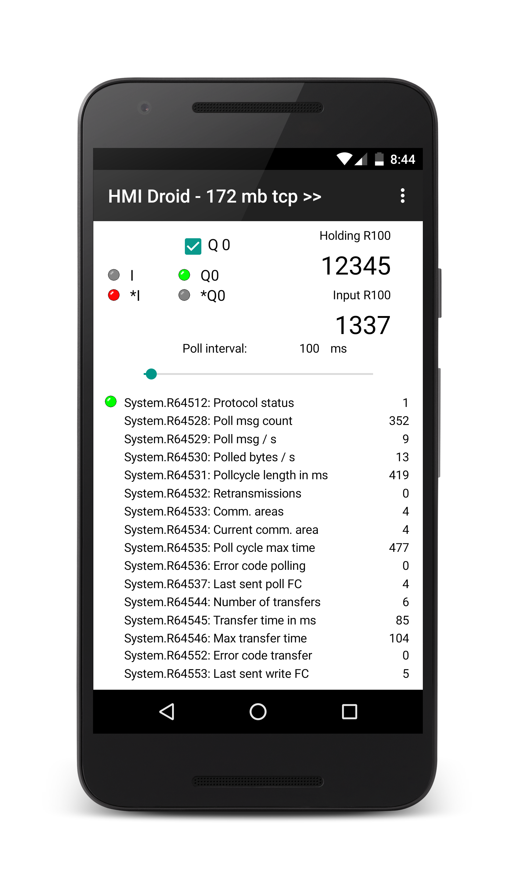
|
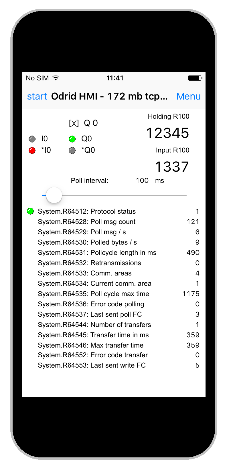
|
The example panel in the screenshots above is available for download.
172 mb tcp.led
Download the file and open it in HMI Droid Studio.
Modify the IP-address in the communication parameters settings to match your PLC/controller.
Use the Test run feature or transfer the file to the Android or iOS-device.
This panel (page) is 320 dp wide. On some devices the panel scaling feature therefore must be enabled to fit the workspace.
Note: This sample panel (page) uses all Modbus data types. The panel (page) can be used with many PLCs without modifications but you may need to change addresses and/or variable areas to use it with your PLC/Controller/Gateway/Frequency converter etc.
System flags
There are a number of boolean variables (flags) in the system variable area which can be used to monitor the communication.| Address | Function |
|---|---|
| 65280 | True when connection with the controller or PLC is established. (System register 65280 = 1.) |
| 64512 | True when the communication protocol in running. (System register 64512 = 1.) |
| 64523 | Reserved for Modbus protocol driver in Waiting for response state. (System register 64523 = 1.) |
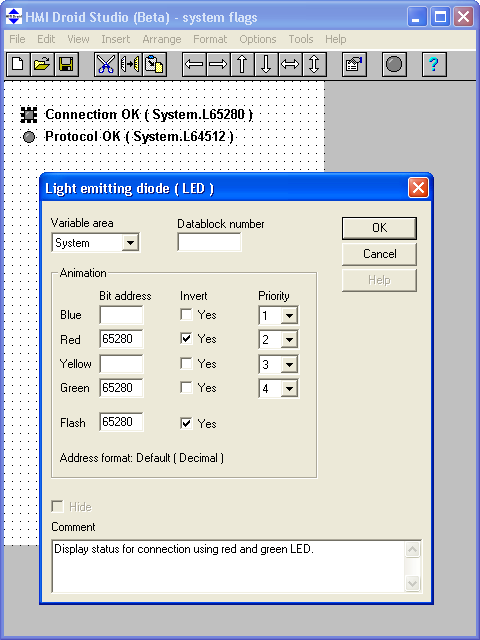
|
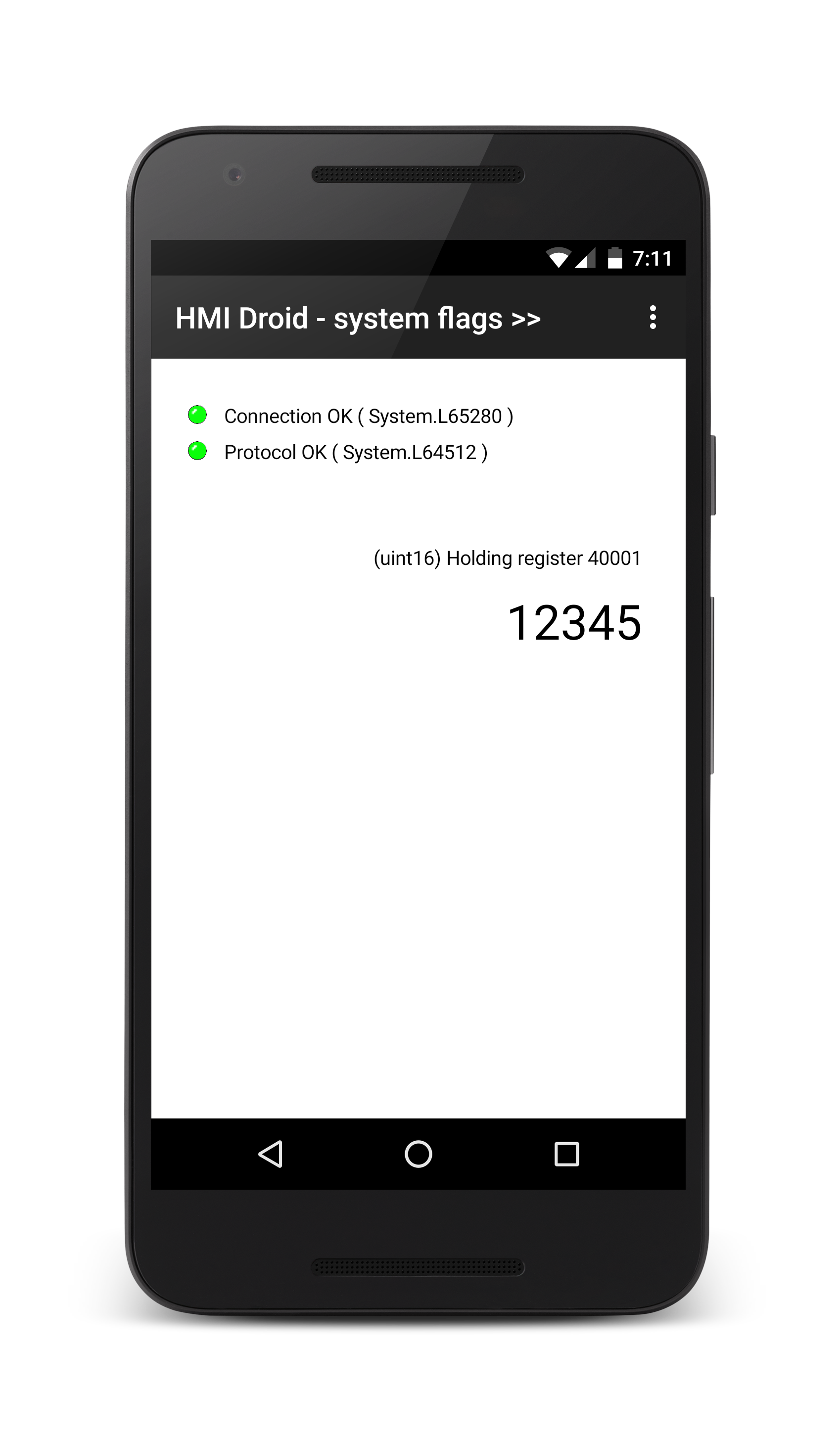
|
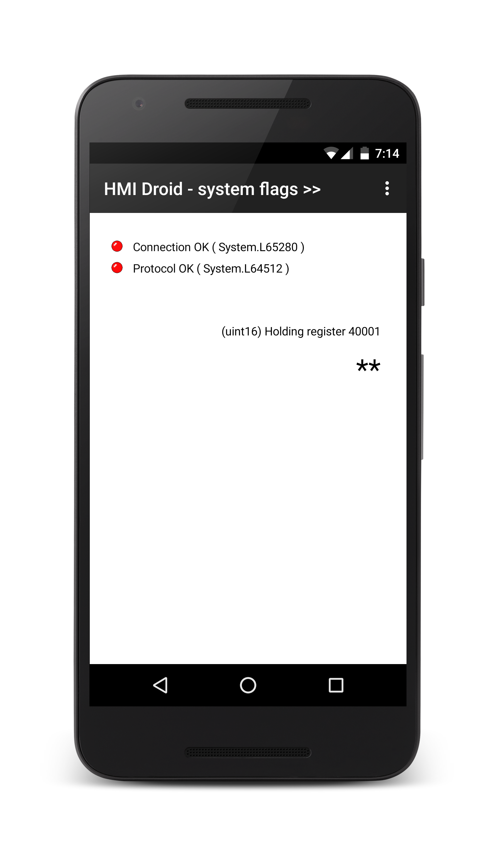
|
The example panel in the screenshots above is available for download.
system flags.led
Download the file and open it in HMI Droid Studio.
Modify the IP-address in the communication parameters settings to match your PLC/controller.
Use the Test run feature or transfer the file to the Android or iOS-device.
This panel (page) is 320 dp wide. On some devices the panel scaling feature therefore must be enabled to fit the workspace.
Test run panel (page)
HMI Droid Studio has a feature for testing panels (pages) without first transfer the panels (pages) to an Android or iOS/macOS device.Currently the test run function supports the Modbus/TCP, Modbus/TCP Class 1, Modbus RTU Class 1 and Siemens S7 Communication (ISO-on-TCP) protocols over TCP/IP. The other protocols and different connection types like Bluetooth SPP and UDP/IP will be added later.
Update: HMI Droid Studio 6.7.8.3111 (Beta) supports Bluetooth SPP.
For Modbus/TCP, the minimum required communication parameters are Connection type that should be set to WiFi (TCP/IP), IP-address (or host name), Port, Protocol, Device ID and Poll interval.
The command "Test panel" in the Options menu is used to start and stop the test run panel (page) mode.
Most of the HMI Droid/Odrid HMI features, including the system registers, are working exactly the same way as on a real Android or iOS/macOS device but navigation between different panels (pages) is not supported and the Change value feature for Numeric variables does not support all formats.
When starting the Test run mode, HMI Droid Studio always makes a plausibility check for the communication parameters for all used channels before the test run mode is entered.
In HMI Droid Studio 6.7.8.3115 and later, there is also a plausibility check for the variable areas in the different objects vs the selected communication protocol for all channels. If a variable area is not supported by the communication protocol, a warning is displayed.
Note: The free-of-charge version of HMI Droid Studio with version lower than 6.7.8.3096 has a time limit of 15 minutes for the test run mode.

|

|

|

|

|

|
Protect panel (page)
A panel (page) can be protected from modification with the command Protect Page in the file menu.Note: Some diagostic features are disabled in the HMI Droid/Odrid HMI apps for protected panels (pages).
Addressing variables in xLogics PLC's
Table showing the principle of how to choose variable area and enter address for accessing the boolean variables in the xLogic/RievTech PLCs with the HMI Droid / Odrid HMI app.| Variable designation in the PLC | Variable area | Address |
|---|---|---|
| I 1 | I | 0 |
| I 2 | I | 1 |
| I 3 | I | 2 |
| I 4 | I | 3 |
| etc | ||
| Q 1 | Q | 0 |
| Q 2 | Q | 1 |
| Q 3 | Q | 2 |
| Q 4 | Q | 3 |
| etc | ||
| B 1 | Q | 256 |
| B 2 | Q | 257 |
| B 3 | Q | 258 |
| B 4 | Q | 259 |
| etc | ||
| F 1 | Q | 1536 |
| F 2 | Q | 1537 |
| F 3 | Q | 1538 |
| F 4 | Q | 1539 |
| etc | ||
Addressing variables in Koyo Click PLC's
Use the Modbus/TCP class 1 selection for protocol.Bit-variables (X/Y/C/CT/SC)
| Address in PLC | Data Type | Modbus 984 address |
Variable area | Variable address |
|---|---|---|---|---|
| X1 | BIT | 100001 | I | 0 |
| X2 | BIT | 100002 | I | 1 |
| X3 | BIT | 100003 | I | 2 |
| etc | ||||
| Y1 | BIT | 8193 | Q | 8192 |
| Y2 | BIT | 8194 | Q | 8193 |
| Y3 | BIT | 8195 | Q | 8194 |
| etc | ||||
| C1 | BIT | 16385 | Q | 16384 |
| C2 | BIT | 16386 | Q | 16385 |
| C3 | BIT | 16387 | Q | 16386 |
| etc | ||||
| T1 | BIT | 145057 | I | 45056 |
| T2 | BIT | 145058 | I | 45057 |
| T3 | BIT | 145059 | I | 45058 |
| etc | ||||
| CT1 | BIT | 149153 | I | 49152 |
| CT1 | BIT | 149154 | I | 49153 |
| CT1 | BIT | 149155 | I | 49154 |
| etc | ||||
| SC1 | BIT | 161441 | I | 61440 |
| SC2 | BIT | 161442 | I | 61441 |
| SC3 | BIT | 161443 | I | 61442 |
Numeric variables (DS/DD/DH/DF)
| Address in PLC | Data Type | Modbus 984 address |
Variable area | Variable address |
|---|---|---|---|---|
| DS1 | INT | 400001 | Register/Default | 0 |
| DS1 | INT | 400002 | Register/Default | 1 |
| DS1 | INT | 400003 | Register/Default | 2 |
| etc | ||||
| DD1 | INT2 | 416385 | Register/Default | 16384 |
| DD1 | INT2 | 416387 | Register/Default | 16386 |
| DD1 | INT2 | 416389 | Register/Default | 16388 |
| etc | ||||
| DH1 | HEX | 424577 | Register/Default | 24576 |
| DH2 | HEX | 424578 | Register/Default | 24577 |
| DH3 | HEX | 424579 | Register/Default | 24578 |
| etc | ||||
| DF1 | FLOAT | 428673 | Register/Default | 28672 |
| DF2 | FLOAT | 428675 | Register/Default | 28674 |
| DF3 | FLOAT | 428677 | Register/Default | 28676 |
Words consisting of bit-variables (XD/YD/TD/CTD/SD)
| Address in PLC | Data Type | Modbus 984 address |
Variable area | Variable address |
|---|---|---|---|---|
| XD1 | HEX | 357345 | AI | 57344 |
| XD2 | HEX | 357347 | AI | 57346 |
| XD3 | HEX | 357349 | AI | 57348 |
| etc | ||||
| YD1 | HEX | 457857 | Register/Default | 57856 |
| YD2 | HEX | 457859 | Register/Default | 57858 |
| YD3 | HEX | 457861 | Register/Default | 57860 |
| etc | ||||
| TD1 | INT | 445057 | Register/Default | 45056 |
| TD2 | INT | 445059 | Register/Default | 45058 |
| TD3 | INT | 445061 | Register/Default | 45060 |
| etc | ||||
| CTD1 | INT2 | 449153 | Register/Default | 49152 |
| CTD2 | INT2 | 449155 | Register/Default | 49154 |
| CTD3 | INT2 | 449157 | Register/Default | 49153 |
| etc | ||||
| SD1 | INT | 361441 | AI | 61440 |
| SD2 | INT | 361442 | AI | 61441 |
| SD3 | INT | 361443 | AI | 61442 |
| etc | ||||
Addressing variables in Schneider Electric Modicon M221 PLC's
Use the Modbus/TCP class 1 selection for protocol.| Variable designation in the PLC | Variable area | Address |
|---|---|---|
| %M0 | Q (Read/Write) or I (Read only) | 0 |
| %M1 | Q (Read/Write) or I (Read only) | 1 |
| %M2 | Q (Read/Write) or I (Read only) | 2 |
| etc | ||
| %MW0 | Register or Default | 0 |
| %MW1 | Register or Default | 1 |
| %MW2 | Register or Default | 2 |
| etc | ||
Eaton easyE4 programmable relays
To use HMI Droid/Odrid HMI with the easyE4, Modbus/TCP must be enabled in the Modbus Tab in Eaton easySoft.
A Modbus map is found on page 559-561 in the manual.
Please note that little-endian is used when converting bytes to words in
an easyE4. If you want to implement Modbus communications with big-
endian, you will need to make the necessary adjustments.
In HMI Droid 1.7.8.116 and Odrid HMI 1.7.0 there is an option Always read full bytes in the settings that must be unselected to read the inputs and outputs in the easyE4.
The option Always read full bytes is also avaiable in HMI Droid Studio 6.7.8.3119 (beta) and located in the Device settings.
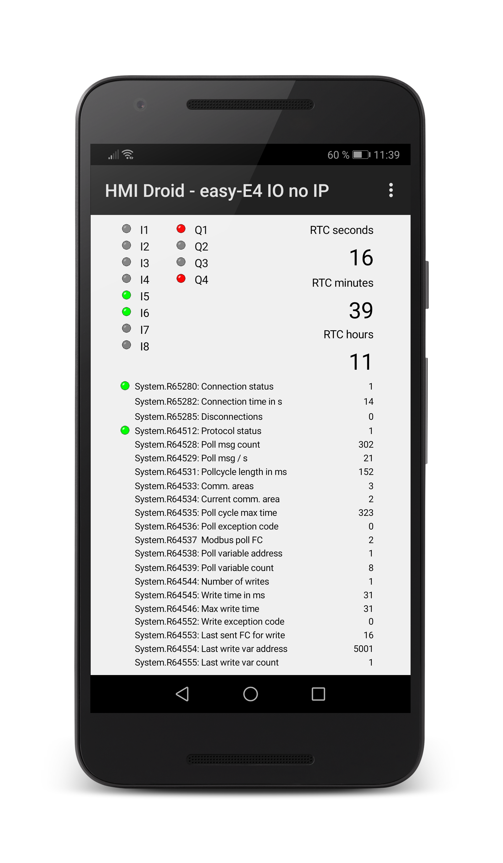
|
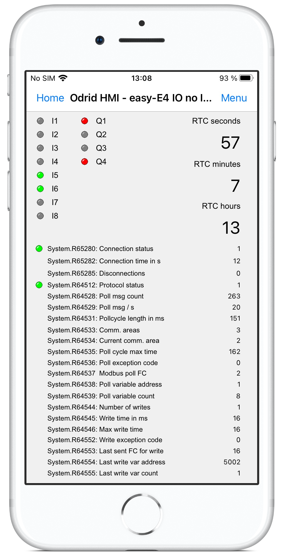
|
The example panel (page) in the screenshot(s) above is available for download.
easy-E4 IO no IP.led
Just download the *.led-file to your Android or iOS-device, enter the IP-address of your Eaton easy-E4 PLC in the settings and unselect the option Read full bytes.
Siemens S7 PLC's
Use the Siemens S7 Communication (ISO-on-TCP) communication protocol.Select the Siemens Address format in the options menu.
Note If datablocks above 255 are used, the setting for Last S7 Datablock in the Android or iOS/macOS device must be increased.
Siemens LOGO!
For the LOGO!, Rack must be 0 and and Slot must be 0.Use the following setup for the LOGO!.
The VM area in the LOGO! is accessed as Datablock 1 in HMI Droid.
NOTE: In LOGO!Soft Comfort V8.3 there is a checkbox "Allow S7 access" in the section Ethernet connections in the General settings tab that must be checked.
Siemens 1200/1500
For the 1200, Rack must be 0 and and Slot must be 1.Only global DBs can be accessed.
The Optimized block access must be turned off.
The access level must be
Full access (no protection)and the
connection mechanismmust
permit access with GET/PUT communication from remote partner.
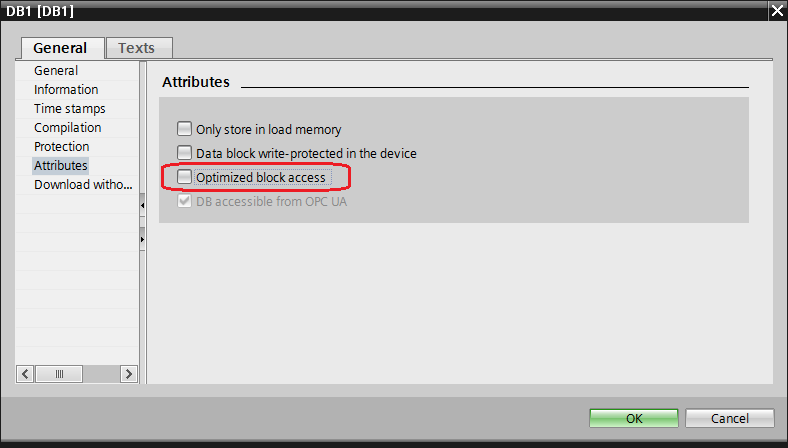
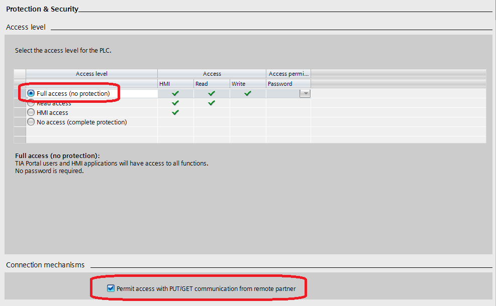
Note: In TIA Portal, it may be necessary to scroll down the view to display the
Permit access with PUT/GET communication from remote partnercheck box.
Customized scaling of analog inputs in a Siemens LOGO!
This is an example of how to scale a PT 1000 temperature sensor with a range of -50 to 500 °C using the As text format by using a text list. The same approach can be used for scaling in other many cases too if no other format will do the job.The range of the analog inputs in the Siemens LOGO! is [0,1000].
A text list can easily be created with a few lines of C code in a on line C compiler by just pasting the output from the program execution into a text file in Notepad.
#include <stdio.h>


int main()

{


    for (int i=0; i<=1000; i++)

    {


        float f = (550.0 * i / 1000.0) - 50.0;


        printf("%i %.1f °C\n", i, f );


    }


    return 0;


}
Content of the text list:
0 -50.0 °C

1 -49.5 °C

2 -48.9 °C

3 -48.3 °C

4 -47.8 °C

5 -47.2 °C

6 -46.7 °C

.

.

.

998 498.9 °C

999 499.5 °C

1000 500.0 °C
Note: It's not recommended to create this kind of text list by hand.
Checklist for troubleshooting communication issues
Setting up the communication for a standard PLC that uses Modbus/TCP is normally quite simple. Other configurations are more complex like e.g. Modbus RTU over Bluetooth.Some ideas for how to proceed systematically.
Always start by monitoring the system registers. These variables provides very useful information about the connection and may also contain different error codes.
The list below is mainly based on a large number of real support cases from the beginning of 2014 and forward.
PLC/Controller configured as server?
HMI Droid/Odrid HMI is always client and will only connect to a device that is server.Correct communication parameters?
Communication parameters entered for the panel (page) will always override any settings in the Android or iOS-device.Press the Menu button and select Diagnotics (Android) or Communication (iOS/macOS) and double check the settings.
Modbus
Modbus/TCP [class 0] can only read and write the Holding Register Modbus data type. Using any of the variable areas Q, I or AI requires Modbus/TCP class 1.The option "32 bit register" must not be checked unless if using a xLogic/RievTech PLC.
Rx timeout must not be too low, the default value is 3000 ms and you should not enter a lower value.
Bluetooth
Make sure the Bluetooth adapter supports SPP.The MAC-address must be entered in uppercase with colon as byte separator and no extra characters. (e.g. AA:BB:CC:DD:EE:FF)
SPP (Serial Port Profile) must be selected.
Have the Bluetooth devices been paired?
Is Bluetooth enabled on the Android device?
Note: iOS devices does not support Bluetooth SPP.
WiFi (TCP/IP) or UDP
Is the IP-address or host name correct?Use a Ping or Traceroute tool to verify that the PLC/controller can be reached.
Is the Port number correct?
Normally the port number should be 502 for Modbus/TCP and 102 for Siemens S7. Use e.g. port 4001 for Modbus RTU on TCP/IP.
Is the Android or iOS-device connected to a guest network with restrictions?
Is the Default gateway and Network Mask setup correctly in the PLC/Controller?
A missing Default gateway will disable connections that requires routing e.g. connections over Internet.
Are there any Access control limitations allowing e.g. only certain IP-addresses or MAC-addresses to connect?
Make sure there is no IP-address conflict.
Serial communication - Bluetooth or Port server
Rx and Tx swapped?Handshaking signals swapped or misconfigured?
Electrical levels OK?
Correct baudrate?
Correct number of databits, stopbits and parity?
Siemens PLC?
Are the values for Siemens S7 Rack and Slot correct?Rack is normally 0. Slot is normally 0, 1 or 2 depending on type of PLC.
If using a CP 343-1, the value for Slot should refer to the CPU and not to the CP.
For Siemens S7 1200, 1500 and LOGO! you need to make certain settings in the PLC. Read the appendices in this manual for LOGO! and 1200/1500 for details.
If using Datablocks above 255, the setting for Last S7 Datablock must be increased in the settings on the Android or iOS device.
Make sure there are enough connection resources in the PLC.
NOTE: The LOGO! only supports one (1) incoming connection when using the Siemens S7 Communication (ISO-on-TCP) protocol.
NOTE: The address range for Datablocks, Inputs, Outputs and Memory is 2048 words (4096 bytes).
Eaton easyE4 PLC?
The option Read full bytes (or Always read full bytes) in the settings for the app must be unselected to be able to read digital inputs and outputs.See appendix Eaton easyE4 programmable relays.
Variables
At least one (1) variable in the panel (page) must read from the PLC/Controller to start the polling.Are the correct variable areas selected?
Siemens S7: Default, Datablock, Memory (M), Input (I), Output (Q).
Modbus: Default, Register, Input (I), Output (Q), Analog input (AI).
Is the variable address correct?
LOGO! M1..M64 = 0..63 in HMI Droid etc.
Modbus R40001 = address 0 in HMI Droid.
Can the variables be read at all from the PLC/controller?
Example: Schneider gateway type SR3NET01BD has gaps in the Modbus map.
Custom Modbus implementation?
The Modbus device must conform to the Modbus specification with respect to Modbus Function Codes and maximum message sizes.Try HMI Droid on a Modbus simulator.
Connection over internet
The IP-address to connect must be public. Some ISP (Internet Service Provider) are using Carrier-grade NAT i.e. the IP-address is a LAN address and not a public IP-adress on the Internet. Make sure your ISP (Internet Service Provider) is not blocking incoming connections.iOS/iPadOS 14
In iOS/iPadOS 14 and later you have to grant the app permission to connect to devices on your local network.Note: The iPhone or iPad will display the message
Odrid HMIwould like to find and connect to devices on your local network at the first connect attempt only. If you choose Don't allow you have to manually enable the LAN access for Odrid HMI in the settings to be able to connect to a PLC or other device in your LAN.
More info here.
Still not working?
Please contact us for further advice.Port server setup example
Some screenshots of a typical setup for a MOXA NPort 5110 port server.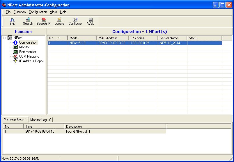
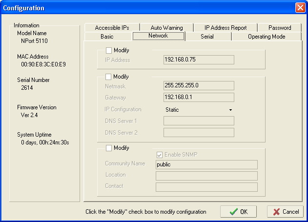
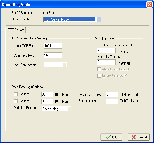
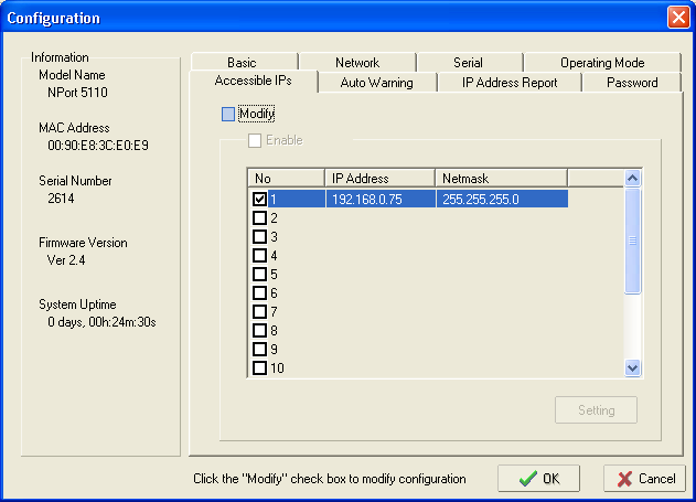
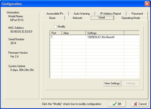
Known issues
| Problem | Platform | Reported | Notes |
|---|---|---|---|
| LED-objects does not work correct in the test run mode in HMI Droid Studio 6.7.8.3126 and 6.7.8.3127. | Windows | 2024-06-18 |
Problem solved in: HMI Droid Studio 6.7.8.3128 (Upcoming beta) |
| Reading the Modbus data type Input Registers does not work correct in the test run mode in HMI Droid Studio 6.7.8.3119 or later. | Windows | 2024-06-11 |
Problem solved in: HMI Droid Studio 6.7.8.3127 (Beta) |
| Reading the Modbus data type Coil with the option Read full bytes does not work correct in the test run mode in HMI Droid Studio 6.7.8.3119 or later. | Windows | 2024-04-18 |
Problem solved in: HMI Droid Studio 6.7.8.3125 (Beta) |
| The As text format is not working correctly for double register/double word variables in the Numeric variable object in the Test run mode in HMI Droid Studio. | Windows | 2024-02-13 |
Problem solved in: HMI Droid Studio 6.7.8.3123 (Beta) |
| Reading boolean variables mapped on bits in the Modbus Input Registers is not working in HMI Droid version 1.7.8.105 to 1.7.8.127. | Android | 2023-08-30 |
Problem solved in: HMI Droid 1.7.8.128 (beta) |
| Using a smaller value for Timeout than the value for Poll interval will break the Modbus RTU communication. | Android | 2023-06-26 |
Problem solved in: HMI Droid 1.7.8.127 (beta) |
| Transparency for image buttons is not working. | iOS | 2023-05-06 |
Problem solved in: Odrid HMI 1.7.5 (beta) |
| Reading from the Siemens S7 data blocks above byte address 4095 can show incorrect values. | All | 2023-04-11 | |
| Very fast swiping when using a button with a password for navigation can make Odrid HMI crash. | iOS. | 2023-02-23 | |
| On some Android devices, trying to scan for available Bluetooth devices instead of entering the MAC-address does not work correctly. |
Android 11 and lower. |
2023-01-31 |
Problem solved in: HMI Droid 1.7.8.124 (beta) |
| On some devices, the app crashes when trying to connect to a Bluetooth device selected from paired devices or available devices instead of entering the MAC-address. |
Android 12 and higher. |
2023-01-14 |
Problem solved in: HMI Droid 1.7.8.123 (beta) |
| Odrid HMI 1.7.0 incorrectly reads the Modbus variables of type Coil and Discrete Input with address 0 as false. | iOS/iPadOS | 2022-11-04 |
Problem solved in: Odrid HMI 1.7.1 (beta) |
| Pressing the back button when on the first page ("start") does not close HMI Droid on devices running Android 12 or later. | Android | 2022-10-02 | This is caused by behavior changes in Android 12, use another method to close the app. |
| The Bar Indicator object is not working with 32-bit variables. | Android and iOS/macOS | 2022-09-10 |
This is described in the manual: Note: Currently only 16 bit integer values are supported but 32 bit integer and floats will be implemented later. Problem solved in: Odrid HMI 1.7.0 (beta) HMI Droid 1.7.8.121 (beta) |
| The app craches if using COMLI with an invalid Device ID. | Android | 2022-06-29 |
Make sure to use a valid Device ID i.e. within the range [1,247]. Problem solved in: HMI Droid 1.7.8.121 (beta) |
|
Image objects are incorrectly positioned under certain circumstances. |
iOS/macOS |
2022-06-12 | Problem solved in Odrid HMI 1.6.9 (Beta). |
|
Image object without filename causes Odrid HMI to crash at launch. |
iOS/macOS |
2022-06-12 | Problem solved in Odrid HMI 1.6.9 (Beta). |
|
Booleans mapped on bits in Modbus Holding registers with register address above 0 can not be manipulated in Odrid HMI 1.6.0, 1.6.1, 1.6.2, 1.6.3 and 1.6.4. |
iOS |
2022-04-22 | Problem solved in Odrid HMI 1.6.5 (Beta). |
|
Reading 32-bit integer and floating point variables with the Modbus protocol drivers always returns 0 in Odrid HMI 1.6.0, 1.6.1 and 1.6.2. |
iOS |
2022-04-07 | Problem solved in Odrid HMI 1.6.4 (Beta). |
|
Writing 32-bit integer variables with the Siemens S7 Communication (ISO-on-TCP) protocol driver does not work in Odrid HMI 1.6.0 and 1.6.1. |
iOS |
2022-04-05 | Problem solved in Odrid HMI 1.6.3 (Beta). |
| Using the new loggning feature in the line graph object with a channel that does not exists causes the app to crash. |
Android |
2022-03-18 |
Problem solved in: HMI Droid 1.7.8.118 (Beta) |
| If Radio buttons are changed faster than the poll interval, they do not update from the current value. |
Android |
2022-01-15 |
Problem solved in: HMI Droid 1.7.8.117 (Beta) |
| Erasing the 'Name' property for a Button object will make HMI Droid Studio crash the next time the dialog for the Button object is closed with the OK button. |
HMI Droid Studio 6.7.8.3103 to 6.7.8.3107. |
2022-01-17 |
Problem solved in: HMI Droid Studio 6.7.8.3108 (Beta) |
| Text on buttons is not centered vertically when the Lock rotation option is selected on older Android devices. | Android. | 2021-12-12 |
Problem solved in: HMI Droid 1.7.8.113 (Beta) |
| During some circumstances, the button actions for manipulating bits does not work correctly when using the Siemens S7 Communication (ISO-on-TCP) communication protocol. | All. | 2021-11-16 |
Problem solved in: HMI Droid 1.7.8.111 (Beta) Odrid HMI 1.5.6 (Beta) HMI Droid Studio 6.7.8.3107 (Beta) |
| Entering a value for Y division larger than Max value - Min value in the Line graph object will cause the app to freeze and generates an ANR (App Not Responding) error in HMI Droid 1.7.8.105 to 1.7.8.108 and in Odrid HMI 1.5.4. | Android and iOS. | 2021-10-11 |
Problem solved in: HMI Droid 1.7.8.109 (Beta) |
| The Numeric variable objects using the fixed decimal formats does not return the correct value when read from the objects area. | Android and iOS. | 2020-11-24 |
Problem solved in: HMI Droid 1.7.8.99 Odrid HMI 1.5.0 (Beta) |
| Occasional crashes when inserting the first panel (page) into an iOS-device using the "Open in..." command in e.g. the email client. | iOS. | 2020-06-02 |
Problem solved in: Odrid HMI 1.4.6 (Beta) |
| The default value for the As Text format in the Numeric variable object is always displayed as "?" regardless the default value set in HMI Droid Studio. | Android and iOS. | 2020-04-22 |
Problem solved in: Odrid HMI 1.4.5 (Beta) |
| The priority parameters for LED-objects are not preserved when using the Edit | Paste and Edit | Undo commands. | HMI Droid Studio 6.7.8.3094 and lower. | 2020-03-04 | Problem solved in HMI Droid Studio 6.7.8.3095. |
Using an incorrect filename for the start.led file e.g. Start.led can cause the panel (page) to be displayed twice.
|
Android | 2019-03-03 | See Naming panels (pages). |
| The Signed fixed decimal format in the Numeric variable object does not work correct with one (1) decimal. | Odrid HMI 1.4.1 and lower. | 2019-10-22 | Problem solved in Odrid HMI 1.4.2 (Beta) published 2019-10-25. |
| Length of full path for image files must not exceed 127 characters. | HMI Droid Studio. | 2019-08-19 | |
| Attempting to save a panel (page) without write privileges in the destination folder is not handled correctly. | HMI Droid Studio 6.7.8.3090 and earlier. | 2019-08-02 | Problem solved in HMI Droid Studio 6.7.8.3091 (Beta) published 2019-09-13. |
| A blank typeface name in the font for an object can cause wrong text size when displayed on the target device. | iOS | 2019-06-17 | |
| The app can crash if using a channel with a higher number than the setting for maximum number of channels. | Android | 2019-03-12 | Problem solved in HMI Droid 1.7.8.94. |
| The Modbus/TCP protocol drivers can not use Device ID > 247. | All | 2019-03-08 |
Problem solved in: HMI Droid 1.7.8.94 Odrid HMI 1.4.0 HMI Droid Studio 6.7.8.3086 |
| On devices with Android version below 5.0 and HMI Droid 1.7.8.90 or higher, the buttons are not displayed correctly regarding the pressed and normal button state. | Android | 2019-01-26 | Problem solved in HMI Droid 1.7.8.92. |
| Siemens S7 Strings with a maximum length > 127 are diplayed as ** and can not be modified. | Android | 2019-01-12 | Problem solved in HMI Droid 1.7.8.92 |
| The Input field, Slider, Line graph, Checkbox and Radio button Objects only works with Channel 0. | iOS | 2019-01-13 | Problem solved in Odrid HMI 1.3.7 |
| The OK button is missing in the Enter value dialog for the Input field object in Odrid HMI 1.3.1 to 1.3.5. | iOS | 2019-01-10 | Problem solved in Odrid HMI 1.3.6 |
| Comments that can be optionally displayed in the Change value/Enter value dialogues, only supports the Western character set. | Android and iOS | 2019-01-03 | Problem solved in HMI Droid 1.7.8.91 and in Odrid HMI 1.3.5 |
| The flash feature for the LED object is not working in Odrid HMI 1.3.0, 1.3.1, 1.3.2 and 1.3.3. | iOS only. | 2018-12-24 | Problem solved in Odrid HMI 1.3.4. |
| The Word swap communication parameter can default to Yes if not controlled from neither the settings in the iOS-device nor from the communication settings for the panel (page) in HMI Droid Studio. | iOS | 2018-12-20 | Problem solved in Odrid HMI 1.3.3. |
| The 16 bit signed fixed decimal point format in the Numeric variable object does not display negative numbers correctly. | iOS and Android versions | 2018-12-18 | Problem solved in HMI Droid 1.7.8.91 and Odrid HMI 1.3.5. |
| Entering av value > 125 for the Modbus Max Block Size parameter in the settings, can cause the Modbus communication to not work properly. | iOS-version. | 2018-12-14 | Problem solved in Odrid HMI 1.3.2. |
| In Odrid HMI 1.3.1, the menu is not displayed on iPad 6th generation (MR7F2NF/A) with iOS 12.1.1. | iOS-version. | 2018-12-13 | Odrid HMI 1.3.1 on iPad air 2 (MH1C2J/A) with iOS 12.1.1. does not have this problem. |
| In Odrid HMI 1.3.0 (Beta) and Odrid HMI 1.2.36, the menu is not displayed on iPads. | iOS-version. | 2018-11-22 | Problem solved in Odrid HMI 1.3.1. |
| In Odrid HMI 1.2.36, the status bar is not displayed in landscape mode on iPhones. | iOS-version. | 2018-10-31 | Problem solved in Odrid HMI 1.3.0. |
| On some devices the app can crash when exiting the settings. | Android-version. | 2018-08-24 | |
| The line chart will only display 50% of the values when using the Siemens S7 Communication protocol. | iOS-version. | 2018-09-02 | Problem solved in Odrid HMI 1.2.36. |
| File names for the panel (page) files must not use upper case characters. | Android-version. | 2018-08-18 | This is by design, see Naming panels (pages). |
| Reading boolean variables from the variable area AI (Analog Inputs) does not work. | Test run mode of HMI Droid Studio and the iOS-version. | 2018-08-11 | Problem solved in HMI Droid Studio 6.7.7.2073 and Odrid HMI 1.2.36. |
| The As Text format in the Numeric variable object does not support multi byte character sets e.g. Chinese. | Android version. | 2018-07-04 | Problem solved in HMI Droid 1.7.8.89 |
| The variable area Objects can not be used for animating image buttons | All. | 2018-06-19 |
Problem solved in: HMI Droid 1.7.8.89 Odrid HMI 1.3.2 HMI Droid Studio 6.7.8.3079 |
S7 and STEP 7 are trademarks of Siemens AG.